Hi All,
I have some questions:
1. My project run on TI-RTOS system. I setting SPI with DMA function, but after my code execute to SPI_transfer() that will stay here. Not continue to execute. Can anyone tell me how to solve it?
In .cfg:
var hwiParams = new halHwi.Params();
/* DMA Hwi for the SPIUSCI driver */
hwiParams.arg = 0;
halHwi.create(50, "&MSP_EXP430F5529LP_isrDMA", hwiParams);
--------------------------------------------
In MSP_EXP430F5529LP.c:
Void MSP_EXP430F5529LP_isrDMA(UArg arg)
{
/* Call the SPI DMA function, passing the SPI handle used for WiFi */
SPI_serviceISR((SPI_Handle) &(SPI_config[0]));
}
/*
* =============================== SPI ===============================
*/
/* Place into subsections to allow the TI linker to remove items properly */
#if defined(__TI_COMPILER_VERSION__)
#pragma DATA_SECTION(SPI_config, ".const:SPI_config")
#pragma DATA_SECTION(spiUSCIBDMAHWAttrs, ".const:spiUSCIBDMAHWAttrs")
#endif
#include <ti/drivers/SPI.h>
#include <ti/drivers/spi/SPIUSCIBDMA.h>
SPIUSCIBDMA_Object spiUSCIBDMAObjects[MSP_EXP430F5529LP_SPICOUNT];
uint8_t spiUSCIBDMAscratchBuf[MSP_EXP430F5529LP_SPICOUNT];
const SPIUSCIBDMA_HWAttrs spiUSCIBDMAHWAttrs[MSP_EXP430F5529LP_SPICOUNT] = {
{
.baseAddr = USCI_B0_BASE,
.clockSource = USCI_B_SPI_CLOCKSOURCE_SMCLK,
.bitOrder = USCI_B_SPI_MSB_FIRST,
.scratchBufPtr = &spiUSCIBDMAscratchBuf[0],
.defaultTxBufValue = 0,
/* DMA */
.dmaBaseAddr = DMA_BASE,
/* Rx Channel */
.rxDMAChannelIndex = DMA_CHANNEL_1,
.rxDMASourceTrigger = DMA_TRIGGERSOURCE_18,
/* Tx Channel */
.txDMAChannelIndex = DMA_CHANNEL_0,
.txDMASourceTrigger = DMA_TRIGGERSOURCE_19
}
};
const SPI_Config SPI_config[] = {
{
.fxnTablePtr = &SPIUSCIBDMA_fxnTable,
.object = &spiUSCIBDMAObjects[0],
.hwAttrs = &spiUSCIBDMAHWAttrs[0]
},
{NULL, NULL, NULL},
};
/*
* ======== MSP_EXP430F5529LP_initSPI ========
*/
void MSP_EXP430F5529LP_initSPI(void)
{
/*
* NOTE: TI-RTOS examples configure USCIB0 as either SPI or I2C. Thus,
* a conflict occurs when the I2C & SPI drivers are used simultaneously in
* an application. Modify the pin mux settings in this file and resolve the
* conflict before running your the application.
*/
/* SPI CLK */
GPIO_setAsPeripheralModuleFunctionOutputPin(GPIO_PORT_P3, GPIO_PIN2);
/* MOSI/SIMO */
GPIO_setAsPeripheralModuleFunctionOutputPin(GPIO_PORT_P3, GPIO_PIN0);
/* MISO/SOMI */
GPIO_setAsPeripheralModuleFunctionInputPin(GPIO_PORT_P3, GPIO_PIN1);
SPI_init();
}
--------------------------------------------
In main.c:
Void spi_master_taskFxn(UArg arg0, UArg arg1)
{
SPI_Handle spi_master;
SPI_Params spi_master_Params;
/* Create I2C for usage */
SPI_Params_init(&spi_master_Params);
spi_master_Params.transferMode = SPI_MODE_CALLBACK;
spi_master_Params.mode = SPI_MASTER;
spi_master_Params.bitRate = 1000000,
spi_master_Params.dataSize = 8;
//spi_master_Params.frameFormat = SPI_POL0_PHA0;
spi_master = SPI_open(Board_SPI0, &spi_master_Params);
if (spi_master == NULL) System_abort("Error Initializing SPI\n");
else System_printf("SPI Initialized!\n");
System_flush();
uint8_t txBuffer[16] = {0xAA, 0xAA, 0xAA, 0xAA, 0xAA, 0xAA, 0xAA, 0xAA,
0xAA, 0xAA, 0xAA, 0xAA, 0xAA, 0xAA, 0xAA, 0xAA};
SPI_Transaction spiTransaction;
spiTransaction.txBuf = txBuffer;
spiTransaction.rxBuf = NULL;
spiTransaction.count = 16;
while(1) {
if(SPI_transfer(spi_master, &spiTransaction) == NULL) System_printf("SPI_transfer error\n");
else System_printf("SPI_transfer success!\n");
System_flush();
}
}
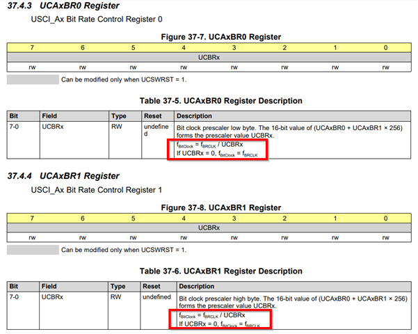
2. When I setting spi_master_Params.bitRate = 1000000, I can measure SPI CLK about 1MHz.
But when I setting to 3000000, it will become 4MHz. Does the limit is 1MHz on TI-RTOS system?
Thanks.