This thread has been locked.

If you have a related question, please click the "Ask a related question" button in the top right corner. The newly created question will be automatically linked to this question.

MSP432E401Y: Hardware not connected w/ BP-ADS7128 module

Part Number: MSP432E401Y
Other Parts Discussed in Thread: BP-ADS7128, , MSP-EXP432E401Y, UNIFLASH

Hi, TI experts,

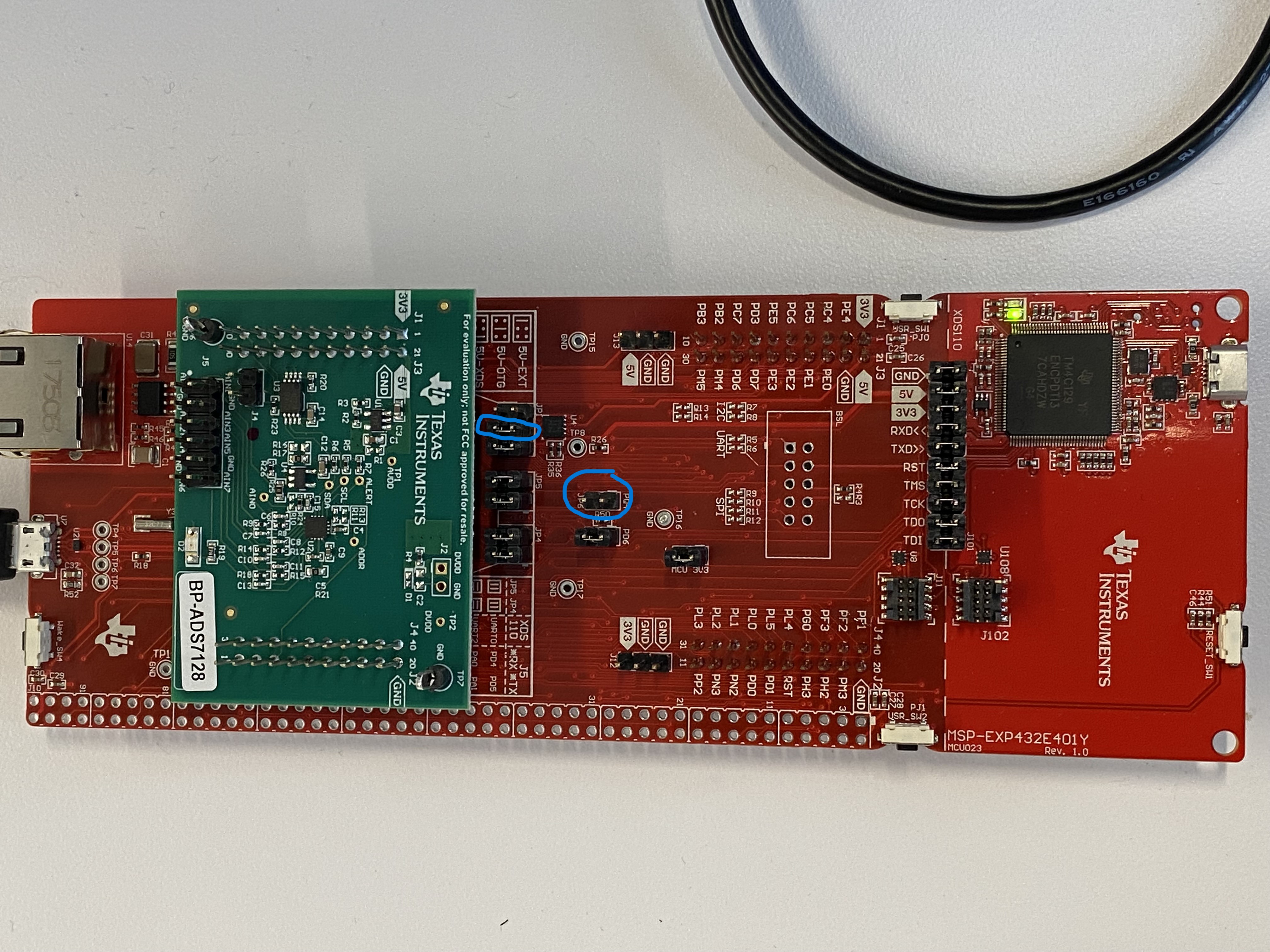
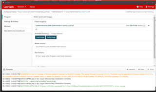
My team procured two MSP432E401Y LaunchPad boards along with a BP-ADS7128 and other eval module. Following the BP-ADS7128 user guide, after completing the step in 3.2.1 stacking the BP-ADS7128 on top of the MSP432E401Y, and connected the USB cable to the data port, I am stuck with the msg showing "Hardware not connected, Please plug your Target Device into your Computer's USB port ...". 

I started a ticket with Bob B at the Data Converter Forum. After some experiment and discussion, he is referring me to the Microcontroller forum here since it's likely the problem is LP board related. Please reference the thread here for background information. 

https://e2e.ti.com/support/data-converters-group/data-converters/f/data-converters-forum/1190763/bp-ads7128-bp-ads7128-hardware-not-connected

Please help. Thank you!

William

  • Hi William,

    From the image you posted here: 

    It looks like you have two jumpers connected to the JP1 header. You should not have two connections on that header, it is only meant to have one connection at a time. Connecting two headers can cause a clash of power sources on the board which could damage it depending on what connections are made at a given time. I will reach out to the data converter team to inform them they need to update their documentation.

    First try and use only a single jumper to get the 5V power to come from only the USB OTG port.

    If not, try and get a fresh board and try and re-program it and make sure only one jumper is used on JP1 to select the correct power sources and then see if the COM port appears on the new board. If it does, then we can assume the prior board was damaged by the dual jumper placement.

    If not, I'll have further ideas for debug, but this is my leading suspect as to what is going awry here. Hopefully just removing the second jumper will resolve it...

    Best Regards,

    Ralph Jacobi

  • Hi, Ralph,

    Thank for the suggestion. I experimented with removing the jumper on pin5/6, while keeping the jumper on pin3/4. After re-connecting the USB cable to the USB OTG port, still no USB devices detected, no new COM port. With jumper 5/6 removed, I can see that the power to the debug port side is gone, and the green LED is off. 

    I only ordered two LP boards, and I followed the setup steps as in the instructions on both boards. I don't have another "fresh" board to try at the moment. 

    Please suggest what other experiments I can try. 

    Thank you!

    William

  • Hi William,

    With jumper 5/6 removed, I can see that the power to the debug port side is gone, and the green LED is off. 

    That's a bit unexpected. Did you remove any jumpers on JP101? Due to the winter storm in Dallas I don't have immediate access to a MSP-EXP432E401Y LaunchPad but I have a sister board that the design was based of and the power LED stays lit on that board when using the same configuration. I'll have to try and test tomorrow if the same is true for the MSP-EXP432E401Y board too.

    For now, let's do the following. First, place the jumper back to the 5/6 so you get power from the XDS connection. Then download CCS UniFlash from TI.com if you haven't already done so.

    I am attaching a .out file to this E2E post, it is the compiled binary for a basic USB application that was developed for the LaunchPad to showcase the USB functionality of the MSP432E4. Using CCS UniFlash with the debug port connected, load this example onto your board.

     usbdevcdcserial_MSP_EXP432E401Y_nortos_ccs.out

    After doing so, either connect a second USB cable without changing the JP1 position OR disconnect the USB cable from the debug port and move it to the port by the Ethernet plug and then change the JP1 jumper to the 3/4 position.

    Look in Device Manager after that and see if you get a USB device showing up. If so, we know the board is working and the USB port is operational. It is possible that the port won't be recognized immediately as a USB device, it would show up with a yellow warning indicator typically if so. If that's the case send me a screenshot of the device manager.

    Best Regards,

    Ralph Jacobi

  • Hi, Ralph,

    All jumpers on J101 are still on. They are there by default. No attempt was made to change the config there. 

    I uploaded the flash with the .out file you provided. See screen shot below. 

    After switching the USB cable back to the data port side, I still don't see any new USB device detected before and after I plug in the cable.(With jumpers on pin3/4 and pin 5/6 at J1) See screen shot below. 

    Thanks!

    William

  • Hi William,

    Thanks for the screenshots, the UniFlash one is good proof that the program loaded correctly without issues which means the device didn't get into a bad / locked state. 

    As I was writing up my post along the lines of this seems to be a damaged board, one more thing I'd like you to check comes to mind. Long shot territory but can you restore the JP6 jumper that was removed? I don't think that jumper impacts the USB example I provided at all, but I'd want to be sure that it doesn't since that is the out-of-the-box jumper configuration.

    Best Regards,

    Ralph Jacobi

  • Hi, Ralph,

    If I move the jumper across the pin 3/4 of JP1 back to JP6, the board will lost power since the USB cable is on the USB OTG side. 

    By restoring the JP6 jumper, you mean to add another jumper at JP6 while keeping the jumper across the pin3/4 of JP1? 

    Regards!

    William

  • Hello William,

    I mean keep just one jumper on JP1 and move the second jumper that had been added to JP6. The single JP1 jumper should be for Pin 3/4 on JP1.

    Best Regards,

    Ralph Jacobi

  • Hi, Ralph,

    I tried both cases, a) jumper on JP1 Pin3/4, no jumper on JP6, b) with jumpers on JP1 Pin3/4 & on JP6 Pin1/2.

    Both cases gave me the same results. No new USB device is detected, and debug port side GREEN LED is off. 

    Regards!

    William

  • Hi William,

    Given what you've tested and the unfortunate misinstruction on that User's Guide, I think the USB connection on the board has been damaged. If you get a new board, use only a single jumper on JP1, and still can't get it to work then message back here. This thread will stay open for 30 days, but if it takes longer than that to get back to it, you can 'Ask a Related Question' and just mention we had this past dialogue.

    I've already sent a message to the data converters team about the documentation issue that led to this. Also you should be able to RMA / get a free replacement for the non-functional board(s) because at this time the root cause appears to be the incorrect documentation.

    Best Regards,

    Ralph Jacobi

  • Hi, Ralph,

    Thank for the update. I ordered two more LP boards to test, and will update here once I receive them. In the meantime, I will RMA the two LP boards I have on hand.

    Regards!

    William

**Attention** This is a public forum