This thread has been locked.

If you have a related question, please click the "Ask a related question" button in the top right corner. The newly created question will be automatically linked to this question.

Infrared Emitting data and Receiving unknown data

Part Number:

Hi, I'm on the way to develop the INFRARED EMITTER.

At the moment, I'm trying to use MSP430FR4133 board with given TI Libraries.

I have two questions;

1.given below code,

unsigned char send_data[8]={0xFF,0xFF,0xFF,0xFF,0x10,0xEF,0xEB,0x14}; Transmitting this data but receiving unknown data.

PLEASE Shear me solution.

2. This code required any library or driver?

#include "msp430.h"

unsigned char IR_code;

unsigned char IR_flag;
unsigned char IR_stop;
unsigned char byte_cnt;
unsigned int bit_sel;
unsigned char *send_addr;


unsigned char send_data[8]={0xFF,0xFF,0xFF,0xFF,0x10,0xEF,0xEB,0x14};   // Unsigned data will displayed

{
    // Watchdog timer works as default setting
    WDTCTL = WDTPW + WDTHOLD;
    
    Init_GPIO();           
    Init_Clock();             
    
    IR_stop = 1;   //disable IR emitter
    
    while(1)
    {
        // clear the flag and counter
        IR_flag = 0;
        byte_cnt = 0;
        bit_sel = 0;
        
        if(IR_stop == 0)
        {
            // Configure IR output pin
            P1SEL0|= BIT0; // use internal IR modulator
            
            // disable Port1 & Port2 interrupt during IR emitting
            P1IE = 0;
            P2IE = 0;
            
            // IR_code = scan_key(); // scan the keypad
            
            // Configure IR modulation: ASK
            SYSCFG1 = IRDSSEL + IREN;
            TA1CCTL0 = CCIE;
            TA1CCTL2 = OUTMOD_7; // output mode: reset/set
            TA0CCTL2 = OUTMOD_7; // output mode: reset/set
            
            // 38kHz 1/4 duty-cycle carrier waveform length setting
            TA0CCR0 = 104;
            TA0CCR2 = 25;
            TA1CCR0 = 640; //the initial time of TA0 should be longer than TA1
            TA1CCR2 = 320;
            
            // set timer operation mode
            TA0CTL = TASSEL_2 + MC_1 + TACLR; //SMCLK, UP mode
            TA1CTL = TASSEL_2 + MC_1 + TACLR; //SMCLK, UP mode
            
            // write button number into buffer
            //send_data[2] = IR_code;
            //send_data[3] = ~IR_code;
            send_addr = &send_data[0];
            
            
            /*while (1) {
            if (buttonPressed) {
            buttonPressed = 0;
            if (!irDataValid) {
            // start IR transmission
            transmitCode(send_data);
        }
        }*/
        
        
        // stop until the end of IR code
        while(IR_stop == 0);
        
        TA0CCTL0 = 0;
        TA0CCTL2 = 0;
        TA0CTL = 0;
        TA0CCR0 = 0;
        TA0CCR2 = 0; //disable timer0
        
        TA1CCTL0 = 0;
        TA1CCTL2 = 0;
        TA1CTL = 0;
        TA1CCR0 = 0;
        TA1CCR2 = 0; //disable timer1
        
        P1IE |= (BIT3 + BIT4 + BIT5); //enable GPIO interrupt
        P2IE |= BIT7;
        
        }
        // __bis_SR_register(LPM3_bits | GIE); //enter low power mode
        IR_stop = 0; // enable IR code emitting
        
    }
}


//********Timer1 interrupt ISR*********//
#pragma vector = TIMER1_A0_VECTOR
__interrupt void TIMER1_A0_ISR (void)
{
switch( TA1IV )
{
case 0:
{
if(IR_flag)
{
IR_stop=1; // stop IR modulator
TA1CCTL0 &= ~CCIE; // disable timer_A0 interrupt

}

if((byte_cnt==0)&& (bit_sel==0)) // leading pulse burst of IR code
{
TA1CCR0 = 53999; // 9ms high
TA1CCR2 = 35999; // 4.5ms low
byte_cnt++; // byte counter
bit_sel++; // bit counter
}
else if((byte_cnt>= 5)&& (bit_sel==1)) // the end of IR code
{
TA1CCR0 = 2249; //0.562ms pulse burst to show the end
TA1CCR2 = 2249;
IR_flag=1;
}
else
{
if((*send_addr & bit_sel) == 0) // data "0"
{
TA1CCR0 = 4499; // 0.562ms high 0.562ms low
TA1CCR2 = 2249;
bit_sel<<=1;
}
else // data "1"
{
TA1CCR0 = 8999; // 0.562ms high 1.687ms low
TA1CCR2 = 2249;
bit_sel<<=1;
}
if(bit_sel>=256) // start a new byte
{
send_addr++;
byte_cnt++;
bit_sel=1;
}
}
break;
}
default: break;
}
}

  • Hi Trupti,

    1.given below code,

    unsigned char send_data[8]={0xFF,0xFF,0xFF,0xFF,0x10,0xEF,0xEB,0x14}; Transmitting this data but receiving unknown data.

    How are you verifying that you are seeing unknown data? Are you watching the RX_Data buffer in the receiver? Are you using another launchpad with the BOOST-IR booster pack as the receiver or something else? The Receiver example code for the MSP430FR4133 and BOOST-IR Boosterpack expects to receive only 4 bytes typically. 

    2. This code required any library or driver?

    Looking at this you would require the code in the HAL files included in the project you are using. As well as the register definitions included in msp430.h.

    I don't believe there is anything else required here, but if there is missing or undefined symbols here, then there should be errors generated when you compile.  

    Best Regards,
    Brandon Fisher

  • I'm using Arduino as the receiver, its possible to receive RX_data?  

  • Hi Trupti,

    I couldn't say what the Arduino you are using is expecting, but it should be possible to receive RX data provided everything is correct.

    What kind of receiver are you using on the Arduino side? Are you sure the carrier frequencies are the same?

    Best Regards,

    Brandon Fisher

  • Hi Brandon Fisher,

    I am using TSOP13238 38kHz AGC2 Receiver.

    In below the code, just disable Keypad section.

    #include "msp430.h"
    #include "HAL_FR4133LP_LCD.h" //Declared and included in Seprate file
    #include "HAL_FR4133LP_Board.h" //Declared and included in Seprate file

    unsigned char IR_code;
    unsigned char IR_flag;
    unsigned char IR_stop;
    unsigned char byte_cnt;
    unsigned int bit_sel;
    unsigned char *send_addr;
    //unsigned char send_data[4]={0x55, 0xaa, 0x00, 0xff};// Unsigned data will displayed
    unsigned char send_data[4]={0x10,0xEF,0xEB,0x14};// Unsigned data will displayed

    int main( void )
    {
    // Watchdog timer works as default setting
    WDTCTL = WDTPW + WDTHOLD;

    Init_GPIO(); //Initialize GPIO
    Init_Clock(); //Initialize Clock
    //Init_keypadIO(); //Initialize Keypad
    Init_LCD(); //Initialize LCD


    LCD_Display_MSP_IR(); // Display "MSP--IR"
    LCD_Display_TX(); // Display "TX"

    IR_stop = 1; //disable IR emitter

    while(1)
    {
    // clear the flag and counter
    IR_flag = 0;
    byte_cnt = 0;
    bit_sel = 0;

    if(IR_stop == 0)
    {
    // Configure IR output pin
    P1SEL0|= BIT0; // use internal IR modulator

    // disable Port1 & Port2 interrupt during IR emitting
    P1IE = 0;
    P2IE = 0;

    // IR_code = scan_key(); // scan the keypad

    // Configure IR modulation: ASK
    SYSCFG1 = IRDSSEL + IREN;
    TA1CCTL0 = CCIE;
    TA1CCTL2 = OUTMOD_7; // output mode: reset/set
    TA0CCTL2 = OUTMOD_7; // output mode: reset/set

    // 38kHz 1/4 duty-cycle carrier waveform length setting
    TA0CCR0 = 104;
    TA0CCR2 = 25;
    TA1CCR0 = 640; //the initial time of TA0 should be longer than TA1
    TA1CCR2 = 320;

    // set timer operation mode
    TA0CTL = TASSEL_2 + MC_1 + TACLR; //SMCLK, UP mode
    TA1CTL = TASSEL_2 + MC_1 + TACLR; //SMCLK, UP mode

    // write button number into buffer
    //send_data[2] = IR_code;
    //send_data[3] = ~IR_code;
    send_addr = &send_data[0];

    // stop until the end of IR code
    while(IR_stop == 0);

    TA0CCTL0 = 0;
    TA0CCTL2 = 0;
    TA0CTL = 0;
    TA0CCR0 = 0;
    TA0CCR2 = 0; //disable timer0

    TA1CCTL0 = 0;
    TA1CCTL2 = 0;
    TA1CTL = 0;
    TA1CCR0 = 0;
    TA1CCR2 = 0; //disable timer1

    P1IE |= (BIT3 + BIT4 + BIT5); //enable GPIO interrupt
    P2IE |= BIT7;

    }
    // __bis_SR_register(LPM3_bits | GIE); //enter low power mode
    IR_stop = 0; // enable IR code emitting

    }
    }

    //********Timer1 interrupt ISR*********//
    #pragma vector = TIMER1_A0_VECTOR
    __interrupt void TIMER1_A0_ISR (void)
    {
    switch( TA1IV )
    {
    case 0:
    {
    if(IR_flag)
    {
    IR_stop=1; // stop IR modulator
    TA1CCTL0 &= ~CCIE; // disable timer_A0 interrupt

    }

    if((byte_cnt==0)&& (bit_sel==0)) // leading pulse burst of IR code
    {
    TA1CCR0 = 53999; // 9ms high
    TA1CCR2 = 35999; // 4.5ms low
    byte_cnt++; // byte counter
    bit_sel++; // bit counter
    }
    else if((byte_cnt>= 5)&& (bit_sel==1)) // the end of IR code
    {
    TA1CCR0 = 2249; //0.562ms pulse burst to show the end
    TA1CCR2 = 2249;
    IR_flag=1;
    }
    else
    {
    if((*send_addr & bit_sel) == 0) // data "0"
    {
    TA1CCR0 = 4499; // 0.562ms high 0.562ms low
    TA1CCR2 = 2249;
    bit_sel<<=1;
    }
    else // data "1"
    {
    TA1CCR0 = 8999; // 0.562ms high 1.687ms low
    TA1CCR2 = 2249;
    bit_sel<<=1;
    }
    if(bit_sel>=256) // start a new byte
    {
    send_addr++;
    byte_cnt++;
    bit_sel=1;
    }
    }
    break;
    }
    default: break;
    }
    }
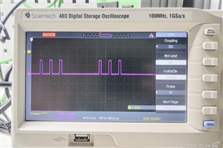
    I am checking output on port P1.0, output pulse is below image. This is correct?

    How to sure the carrier frequencies are the same?

  • "IR Remote" includes a variety of protocols, mostly not-interoperable. I don't recall which one the BOOST-IR firmware uses.

    There are Arduino libraries which can deduce and decode many/most of the common protocols. Here's one that 2-minutes-with-Google turned up:

    https://learn.sparkfun.com/tutorials/ir-communication/all

    It appears that, even if that library can't figure out what protocol it is, it will give you the received codes so you can detect them in your code.

  • this is output is correct?

    I am checking output on port P1.0, output pulse.

  • The period for a 38kHz (carrier) signal is about 26usec, so these pulses look about right. What's more interesting is the higher-level pattern of these pulses (zoom out on your scope).

    More generally, I think you aren't having trouble with your 38kHz (TSOP) receiver device, since your application is reporting "unknown codes" rather than [nothing at all]. Does your application say anything else about what it received?

  • 10-minutes-with-Google suggests that the BOOST-IR example firmware uses the "NEC IR" protocol (562us pulse separated by either 562us off (0) or 1.7us off (1), though there's more to it):

    https://techdocs.altium.com/display/FPGA/NEC+Infrared+Transmission+Protocol

    Does your library know this protocol?

    [Edit: Minor clarification]

**Attention** This is a public forum