This thread has been locked.

If you have a related question, please click the "Ask a related question" button in the top right corner. The newly created question will be automatically linked to this question.

MSP430F5529: UART Echo Demo not working

Part Number: MSP430F5529

Hi,

I'm working with the MSP430F5529LP and trying to run the UART demo program. I have an RS485 module connected to the TI LaunchPad via the mikroBUS. When running the demo I see the UCA0RXBUF register receiving the correct ascii character over the RS485 cable sent via TeraTerm from my laptop. However, I don't see an echo in TeraTerm. Can you please help me find the problem? Perhaps the problem is with the jumper settings I have, I'm using what was configured on the LaunchPad by default (RX, TX, 5V, 3.3V, GND, SBWDIO, SBWTCK shorted), but the demo doesn't suggest how to configure these. I've also shown the settings I'm using in TeraTerm below.

Note: The RS485 Click module uses a pin to switch it between tx/rx mode. This pin is located on Port 2.1 (This is PWM1 of the mikroBUS connector).

Note: I'm also a newbie when it comes to TI Microcontrollers.

www.mikroe.com/rs485-5v-click

  • 1) The first trouble you'll have is that the ADM485 really wants to run at 5V. The Launchpad does have a +5V supply, but connecting the RO pin (at 5V) to the MSP430 UART pin (max 3.6V) could damage the chip. The DI pin may also not respond at 3.3V (I don't see Vih/Vil in the ADM485 datasheet). It looks like there's a 3.3V variant of the Click board:

    https://www.mikroe.com/rs485-33v-click

    2) The F5529 Echo example uses UCA0, so the pins of interest are P3.3/P3.4 (TXD/RXD), top-left next to each other on J1. [Ref data sheet (SLAS590P) Table 9-48].

    3) /RE has a pulldown on the Click, so if you don't do anything it's always in receive mode (this might be why you seem to be succeeding that far). If you change the code (ISR) to set P2.1 as an output and drive it high (P2DIR.1=1, P2OUT.1=1) that should allow you to transmit.  [See also (1) above.] Monitor UCA0STATW:UCBUSY to make sure the byte has been sent before setting /RE low again.

    [Edit: Fixed typo.]

  • Wow,

    HI Bruce thanks for the quick reply and useful information. I've been playing with the code, what I have implemented is shown below. I added in the changes to toggle Port 2 pin 1, but to no avail. I'm still reading data from the RS485 chip into the microcontroller. I also changed the baud rate to 9600, slowing it down. Additionally, I didn't find a SFR called UCA0STATW, but I did find UCA0STAT.

    Note: I'm curious why this device has a single interrupt vector for both TX/RX, the header file shows that they aren't independent.

    #include <msp430.h>

    #define LED BIT0

    void InitializeUART();
    void SendChar(char c);

    int main(void)
    {
        WDTCTL = WDTPW | WDTHOLD; // stop watchdog timer
        P1DIR |= LED; // set P1.0 as output
        InitializeUART(); // initialize UART module
        __enable_interrupt(); // enable global interrupts
        while(1)
        {
            // do nothing
        }
    }

    void InitializeUART()
    {
        P3SEL |= BIT3 + BIT4; // set P3.3 and P3.4 as UART TX and RX
        UCA0CTL1 |= UCSSEL_2; // use SMCLK as UART clock source
        UCA0BR0 = 104; // set baud rate to 9600
        UCA0BR1 = 0;
        UCA0MCTL = UCBRS0;
        UCA0CTL1 &= ~UCSWRST; // release UART module from reset
        UCA0IE |= UCRXIE;  // enable UART receive interrupt

        //Set Read Mode on RS485 module (via PWM1 port 2.0)
        P2DIR |= 0xFF; // All P2.x outputs
        P2OUT &= 0x00; // All P2.x reset (sets UART to Read Mode)
    }

    void SendChar(char c)
    {
        while(!(UCA0IFG & UCTXIFG)); // wait for UART TX buffer to be empty
        UCA0TXBUF = c; // send character
        while(UCA0STAT & UCBUSY);
    }

    #pragma vector=USCI_A0_VECTOR
    __interrupt void USCI_A0_ISR(void)
    {
        switch(UCA0IV)
        {
            case 2: // UCRXIFG
                P1OUT ^= LED; // toggle LED
                char c = UCA0RXBUF; // read received character
                P2OUT |= BIT1; // All P2.x reset (sets UART to Read Mode)
                SendChar(c); // echo back the character
                P2OUT &= 0x00; // All P2.x reset (sets UART to Read Mode)
                break;
            default:
                break;
        }
    }

  • I don't see anything obviously wrong with your code.

    Are you still working with the 5V Click board? I didn't find Vih in the ADM485 data sheet, so it's possible it isn't seeing the (3.3V) transitions on DI and/or /RE. (It's also not a good idea to put 5V on an MSP430 pin, even if it seems to work for a while.)

    What's at the other end of the RS-485 bus (at the PC)? A scope on the signal lines (J4 on the Click) would probably be useful.

    In my experience having a single IRQ for a peripheral (RX+TX+miscellaneous) isn't so unusual.

  • True,

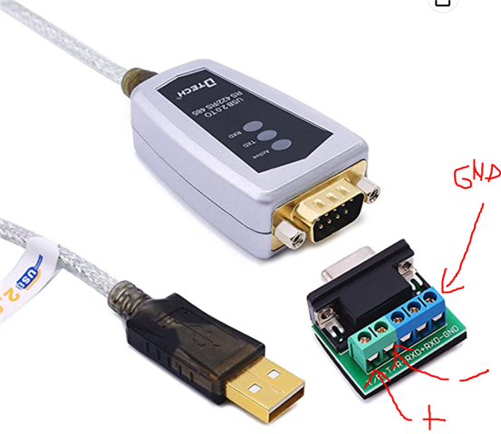
    an oscilloscope is a good next step. Ill give that a try when I have a scope next week. Yes I'm still using the 5V Click board and its reading values from my Laptop of Tera Term correctly. I'm using a USB to RS485 cable (DTech USB to RS422 RS485) link below. Should I be using flow control, since were using the RX/TX enable between the microcontroller and V5 Click?

    https://www.amazon.com/Serial-Converter-Adapter-Supports-Windows/dp/B076WVFXN8/ref=sr_1_4?crid=3ZN7Y81LLIL8&keywords=usb%2Brs485&qid=1676770312&sprefix=usb%2Brs485%2Caps%2C170&sr=8-4&th=1

    RS485 Adapter (and connections)

    V5 Click (And Connections)

    V5 Click Schematic

    Breaking in ISR (ASCII for A, which was typed in Tera Term)

    Tera Term Settings

  • I don't think flow control is relevant here, since there's no flow control over the bus in any case.

    I still suspect the trouble is that you're trying to use a 5V device with a 3V MCU. A scope on the bus (and maybe R/T) may be the only way to find out.

  • I'll definitely do that,

    soon as I have access to the device (which won't be until later next week). In the mean time I'm left to make assumptions. I see what you mean by not needing flow control, since we are not using a signal for this over the bus (just 2 wires, for the half-duplex TX/RX channel). And a ground connection here as well, which may or may not be needed (any thoughts on that?). Why do you suspect the micro-controller being a 3V device? From the datasheet for the ADM485 the limits on the DI input to the device from the micro-controller are -0.3V to 7.3V.

    I'll follow up with you again after setting this to a scope.

  • The MSP430 is a 3.3V (more or less) device while this RS485 driver is a 5V device. This will cause trouble for the MSP430 when its RXD input is driven above Vcc. Forward biasing the protection diode. (See data sheet for diode current limits.) Plus of course maybe raising Vcc unless you are using a shunt regulator. (A series resistor can limit these fault currents to safe levels.)

    RS485 is a three wire interface. You have to have something to reference the differential voltages to. (Those common mode voltage limits in the data sheet.) I always recommend reading a classic article from Circuit Cellar magazine titled "The Art and Science of RS485". Google usually turns up a readable copy.

**Attention** This is a public forum