This thread has been locked.

If you have a related question, please click the "Ask a related question" button in the top right corner. The newly created question will be automatically linked to this question.

MSP430FR2475: Backchannel UART question

Part Number: MSP430FR2475
Other Parts Discussed in Thread: MSP-FET

Hi TI team,

I would like to request help using the backchannel UART of the MSP-FET debugger connected to the MSP430 microcontroller, please refer to our schematic below for the discussion.

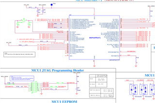
We have a programming process where we attach the MSP-FET (2 wire JTAG) to the H7 programming header and flash the microcontroller image.  Then, we remove the H7 header and separately attach a UART connection (such as FTDI232RL) to the H7 header at pin 5 and 7 to confirm the MCU is now printing out the correct bootup log information to the UART.

I would like to ask if it's possible to use the backchannel UART feature of the MSP-FET to read the MCU's serial debug output.  That way we could avoid needing the separate FTDI232RL device to read the UART.

I could not find enough detail in how to enable this connection so thanks in advance for any help.

Arthur

  • I believe there is a way to re-route the stdio output to the uart. However, it might be easier to just roll your own, and create your own debugging facility with the uart.

  • Hello Arthur,

    You have to connect the UART to the MSP-FET at the appropriate spot on the JTAG header (or sky wire directly to MSP-FET). See MSP Debugger's UG, Section 5.6.  By default, the backchannel UART is enabled and you just have to connect to it via COM port. You can do this in a terminal inside CCS even. It will be labeled MSP430 Application UART within your Device Manager. 

  • Yes, but how do you reroute stdio through it?

  • Hi Jace, 

    When I plug in the debugger to my PC, I do see the Application UART COM port in Device Manager.  I tried opening it in PuTTy but didn't see any output.  I wasn't sure what baud rate to set.

    "You have to connect the UART to the MSP-FET at the appropriate spot on the JTAG header (or sky wire directly to MSP-FET)"

    I see from Figure 5.6.5.1 in SLAU647O that on the MSP-FET 14-pin JTAG connector, pin 12 is UART_TXD and pin 14 is UART_RXD.  Referring to the schematic I shared, does this mean I should wire Header 7 pin 7 (MCU TX) to pin 14 (UART_RXD) on the MSP-FET JTAG connector?  And Header 7 pin 5 to pin 12 on the MSP-FET JTAG connector?  If I do this then I will start to see the UART traffic appearing from the UART COM port I see in Device Manager?

  • By default, the UART will not output anything until you tell it to output something. Look at the UART loopback example.

  • Keith,

    That process I have not done. Typically, my application is just transmitting UART, and not using stdio for messages. Take the UART ECHO code example for instance. 

  • Arthur,

    You won't seen any output via your terminal until the UART is routed through the MSP-FET. As you can see from the MSP Debuggers UG I linke dot earlier, you would need to route the UART to positions 12 and 14. See below.  Note: unlike most UART connections, the header to the MSP-FET is labeled with the target device in mind. This means you do not cross UART TX and RX like you would when going from chip to chip. 

**Attention** This is a public forum