Hello,
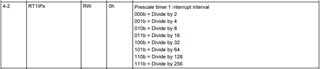
For the following RTC example below, how is the interrupt triggered every 1 second? If I did the math correctly, the output of RT1PS is 250 Hz: 34KHz/4 (RTCPS0CTL divides by 4) /16 (RTCPS1CTL divides by 16).
So at 250Hz, the period would be given as .004 seconds. How does the code make this toggle the LED every 1 second?
/* --COPYRIGHT--,BSD_EX
 * Copyright (c) 2012, Texas Instruments Incorporated
 * All rights reserved.
 *
 * Redistribution and use in source and binary forms, with or without
 * modification, are permitted provided that the following conditions
 * are met:
 *
 * *  Redistributions of source code must retain the above copyright
 *    notice, this list of conditions and the following disclaimer.
 *
 * *  Redistributions in binary form must reproduce the above copyright
 *    notice, this list of conditions and the following disclaimer in the
 *    documentation and/or other materials provided with the distribution.
 *
 * *  Neither the name of Texas Instruments Incorporated nor the names of
 *    its contributors may be used to endorse or promote products derived
 *    from this software without specific prior written permission.
 *
 * THIS SOFTWARE IS PROVIDED BY THE COPYRIGHT HOLDERS AND CONTRIBUTORS "AS IS"
 * AND ANY EXPRESS OR IMPLIED WARRANTIES, INCLUDING, BUT NOT LIMITED TO,
 * THE IMPLIED WARRANTIES OF MERCHANTABILITY AND FITNESS FOR A PARTICULAR
 * PURPOSE ARE DISCLAIMED. IN NO EVENT SHALL THE COPYRIGHT OWNER OR
 * CONTRIBUTORS BE LIABLE FOR ANY DIRECT, INDIRECT, INCIDENTAL, SPECIAL,
 * EXEMPLARY, OR CONSEQUENTIAL DAMAGES (INCLUDING, BUT NOT LIMITED TO,
 * PROCUREMENT OF SUBSTITUTE GOODS OR SERVICES; LOSS OF USE, DATA, OR PROFITS;
 * OR BUSINESS INTERRUPTION) HOWEVER CAUSED AND ON ANY THEORY OF LIABILITY,
 * WHETHER IN CONTRACT, STRICT LIABILITY, OR TORT (INCLUDING NEGLIGENCE OR
 * OTHERWISE) ARISING IN ANY WAY OUT OF THE USE OF THIS SOFTWARE,
 * EVEN IF ADVISED OF THE POSSIBILITY OF SUCH DAMAGE.
 *
 *******************************************************************************
 *
 *                       MSP430 CODE EXAMPLE DISCLAIMER
 *
 * MSP430 code examples are self-contained low-level programs that typically
 * demonstrate a single peripheral function or device feature in a highly
 * concise manner. For this the code may rely on the device's power-on default
 * register values and settings such as the clock configuration and care must
 * be taken when combining code from several examples to avoid potential side
 * effects. Also see www.ti.com/grace for a GUI- and www.ti.com/msp430ware
 * for an API functional library-approach to peripheral configuration.
 *
 * --/COPYRIGHT--*/
//******************************************************************************
//  MSP430FR69xx Demo - RTC in Counter Mode toggles P1.0 every 1s
//
//  This program demonstrates RTC in counter mode configured to source from ACLK
//  to toggle P1.0 LED every 1s.
//
//                MSP430FR6989
//             -----------------
//        /|\ |                 |
//         |  |              XIN|--
//         ---|RST              |  32768Hz
//            |             XOUT|--
//            |                 |
//            |             P1.0|-->LED
//
//   William Goh
//   Texas Instruments Inc.
//   August 2014
//   Built with IAR Embedded Workbench V5.60 & Code Composer Studio V6.0
//******************************************************************************

#include <msp430.h>

int main(void)
{
    WDTCTL = WDTPW | WDTHOLD;               // Stop WDT

    P1OUT &= ~BIT0;
    P1DIR |= BIT0;

    PJSEL0 = BIT4 | BIT5;                   // Initialize LFXT pins

    // Disable the GPIO power-on default high-impedance mode to activate
    // previously configured port settings
    PM5CTL0 &= ~LOCKLPM5;

    // Configure LFXT 32kHz crystal
    CSCTL0_H = CSKEY >> 8;                  // Unlock CS registers
    CSCTL4 &= ~LFXTOFF;                     // Enable LFXT
    do
    {
      CSCTL5 &= ~LFXTOFFG;                  // Clear LFXT fault flag
      SFRIFG1 &= ~OFIFG;
    } while (SFRIFG1 & OFIFG);              // Test oscillator fault flag
    CSCTL0_H = 0;                           // Lock CS registers

    // Setup RTC Timer
    RTCCTL0_H = RTCKEY_H;                   // Unlock RTC

    RTCCTL0_L = RTCTEVIE;                   // RTC event interrupt enable
    RTCCTL1 = RTCSSEL_2 | RTCTEV_0 | RTCHOLD; // Counter Mode, RTC1PS, 8-bit ovf
    RTCPS0CTL = RT0PSDIV1;                  // ACLK, /8
    RTCPS1CTL = RT1SSEL1 | RT1PSDIV0 | RT1PSDIV1; // out from RT0PS, /16

    RTCCTL1 &= ~(RTCHOLD);                  // Start RTC

    __bis_SR_register(LPM3_bits | GIE);     // Enter LPM3 mode w/ interrupts enabled
    __no_operation();

    return 0;
}

#if defined(__TI_COMPILER_VERSION__) || defined(__IAR_SYSTEMS_ICC__)
#pragma vector=RTC_VECTOR
__interrupt void RTC_ISR(void)
#elif defined(__GNUC__)
void __attribute__ ((interrupt(RTC_VECTOR))) RTC_ISR (void)
#else
#error Compiler not supported!
#endif
{
    switch(__even_in_range(RTCIV, RTCIV_RT1PSIFG))
    {
        case RTCIV_NONE:      break;        // No interrupts
        case RTCIV_RTCOFIFG:  break;        // RTCOFIFG
        case RTCIV_RTCRDYIFG: break;        // RTCRDYIFG
        case RTCIV_RTCTEVIFG:               // RTCEVIFG
            P1OUT ^= BIT0;                  // Toggle P1.0 LED
            break;
        case RTCIV_RTCAIFG:   break;        // RTCAIFG
        case RTCIV_RT0PSIFG:  break;        // RT0PSIFG
        case RTCIV_RT1PSIFG:  break;        // RT1PSIFG
        default: break;
    }
}