This thread has been locked.

If you have a related question, please click the "Ask a related question" button in the top right corner. The newly created question will be automatically linked to this question.

MSP430FR2522: Specification on VLO

Part Number: MSP430FR2522


Hi team,

  1. Could you share the max / min number for VLO at LPM 3, 4 ? Datasheet says the typical number is 15% but there is no description for max / min number in the datasheet.
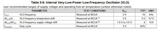
  2. Table 5-8 in the datasheet mentioned there is two types of drift which one is temperature drift and the other is voltage drift.
    Is it to OK that the frequency has 0.5 % drift per 1C because temperature drift has 0.5%/C in the datasheet. And regarding voltage drift, is it ok that the frequency has 4% drift per 1V ? In this case, what is the voltage that there is no drift by supply voltage ?


Thank you and best regards,

Michiaki Tanii

  • Hi Tanii

    Q: Could you share the max / min number for VLO at LPM 3, 4 ? Datasheet says the typical number is 15% but there is no description for max / min number in the datasheet.

    A: Internal Very-Low-Power Low-Frequency Oscillator focuses on system low power performance. it is not the clock with high accuracy. So, there is no max /min data on date sheet. could you please explain the background of this parameter requirement?

    Q: Is it to OK that the frequency has 0.5 % drift per 1C because temperature drift has 0.5%/C in the datasheet

    A: Yes. typcal 0.5% frequency drift at 1 degree temperature drift 

    Q: is it ok that the frequency has 4% drift per 1V 

    A; Yes. Typically 4% frequency drift at 1V voltage drift 

    Q: In this case, what is the voltage that there is no drift by supply voltage ?

    A: There is no standard supply voltage here because the parameter is on the frequency difference (drift).

    Thanks!

  • Historically (other MSP430 series) the VLO is rated at +/-50%, with a center vaguely similar to 10kHz. I personally have seen something like 8-12kHz (without looking very hard).

    Supposing the VLO implementation in the FR2 series is the same, I suspect the -15% for LPM3/4 (in the FR2 series) is additive to this range, since I haven't seen the LPM thing in other series.

    SLAA340 shows how to calibrate the VLO (e.g. SMCLK-ticks/VLO-tick) on an F2-series device. I expect the method could be adapted to the FR2:

    https://www.ti.com/lit/ml/slaa340a/slaa340a.pdf

    That said: This is just context; I don't know why there's no range specification for the FR2 series.

  • Hi Xiaodong,

    Q: Internal Very-Low-Power Low-Frequency Oscillator focuses on system low power performance. it is not the clock with high accuracy. So, there is no max /min data on date sheet. could you please explain the background of this parameter requirement?

     A :  makes the period to capture capacitive sensor during sleep mode and the tolerance of VLO brings the response time. Customer needs to understand the worst case for response time and they need the max / min number. Please share the max / min number for VLO.


    Regarding drift for temperature and supply voltage.

    Could you share the condition(reference) for temperature drift and supply voltage drift ? For example, if the condition Ta = 25C, customer can calculate the tolerance at 65C as below.

    • The drift for temperature at 65C is (65C – 25C) * 0.5%/C = 20%


    Thank you and best regards,

    Michiaki Tanii

  • using DCO clock to meaure VLO clock. I think this method is suitable on MSP430FR device as well.

    Thanks Bruce!

  • Hi Tanii-san

    Q: makes the period to capture capacitive sensor during sleep mode and the tolerance of VLO brings the response time. Customer needs to understand the worst case for response time and they need the max / min number. Please share the max / min number for VLO.

    A: Yes. I can understand the background of customer requirement on max / min frequecy reduced from active mode to LPM3/4 mode. I checked the internal system, we don't have this max/min data here. Please check customer if they can accept the typical 15% parameter here. I think they can test several device to check the read frequency reduced data.

    Q: Could you share the condition(reference) for temperature drift and supply voltage drift ? For example, if the condition Ta = 25C, customer can calculate the tolerance at 65C as below.The drift for temperature at 65C is (65C – 25C) * 0.5%/C = 20%

    A: according to data sheet, the condition is 3V. at the same time, 0.5%/C is the typical data as well.

    Thanks!

  • Hi Xiaodong,

    Q: makes the period to capture capacitive sensor during sleep mode and the tolerance of VLO brings the response time. Customer needs to understand the worst case for response time and they need the max / min number. Please share the max / min number for VLO.

    A: Yes. I can understand the background of customer requirement on max / min frequecy reduced from active mode to LPM3/4 mode. I checked the internal system, we don't have this max/min data here. Please check customer if they can accept the typical 15% parameter here. I think they can test several device to check the read frequency reduced data.


    [MIchiaki] Let me discuss it internally.


    Q: Could you share the condition(reference) for temperature drift and supply voltage drift ? For example, if the condition Ta = 25C, customer can calculate the tolerance at 65C as below.The drift for temperature at 65C is (65C – 25C) * 0.5%/C = 20%

    A: according to data sheet, the condition is 3V. at the same time, 0.5%/C is the typical data as well.


    [Michiaki] It means that the specification of temperature drift and supply voltage drift is based on Ta = 25C and Vcc 3V ?
    In other words, the total drift for temperature can calculate from differentiation for Ta = 25C. and regarding supply voltage drift, the reference should be Vcc = 3V. Is my understanding correct ?


    Thank you and best regards,

    Michiaki Tanii

  • Hi Tanii-san

    [Michiaki] It means that the specification of temperature drift and supply voltage drift is based on Ta = 25C and Vcc 3V ?
    In other words, the total drift for temperature can calculate from differentiation for Ta = 25C. and regarding supply voltage drift, the reference should be Vcc = 3V. Is my understanding correct ?

    VLO frequency temperature drift condition is 3V

    VLO frequency supply voltage drift condition is 1.8 V to 3.6 V

    the frequency drift is the frequency difference. So, there is no the "standard".

    for example. we can calculate the frequency difference is 5% from 25C to 35C at Vcc is 3V.

    Thanks!

  • Hi Xiaodong,


    Could you share the temperature condition at Vcc = 3V, Typ 10kHz ?

    Thank you and best regards,

    Michiaki Tanii

  • Hi Tanii-san

    I think your question has been solved on our mail discussion.

    Please help to click the solved button

  • Hi Xiaodong,

    Could please advise the temperature condition for Typ 10kHz at Vcc = 3V ?

    Best regards,

    Michiaki Tanii

  • Hi Tanii-san

    The temperature condition is the full temperation range.

    Thanks

  • Hi Xiaodong,


    Is it true fVLO : typ 10kHz at Vcc 3V over recommended operating temperature ? If so, how should customer handle the VLO frequency temperature drift 0.5%/C ?

    For example, a device has 10kHz at Vcc 3V , 0C, another device has 10kHz at Vcc 3V, 85C. Is my understanding correct ?


    Thank you and best regards,

    Michiaki Tanii

  • Hi Tanii-san

    as we discussed. 10KHz is the typic value. The test condition of this typic value is 3V and the full temperature range.

**Attention** This is a public forum