This thread has been locked.

If you have a related question, please click the "Ask a related question" button in the top right corner. The newly created question will be automatically linked to this question.

MSP430FR6047: 8 Mux LCD issue

Part Number: MSP430FR6047

Hello, 

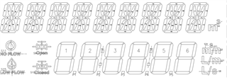
I am using MSP430FR6047 microcontroller. Interfacing a 8-mux LCD with this. 

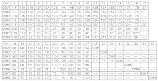
8common lines and 27 segments lines are in use. 

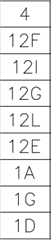
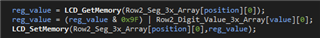
Every segment line 5bits are controlling 1st number row and last 3 bits are controlling 2nd number row. 

To display number in 1st number row using 0-4bit, whatever value I am updating for 0-4bits reflects in LCD properly. 

When trying to display number in 2nd number row using 5-7bits, even if I update  a single bit in 5-7bits all segments getting enabled. 

What could be the issue here.? Please anyone support for the same. 

  • Hello,

    Apologies for the delay, can you provide more details as to what you are doing? As in, what pins are you using, some of your code, etc. I wonder if you are accidentally enabling segments when updating bits in 5-7 bits. 

    You can also reference this Application Report for information on working with segment LCD's.

    Thank you,

    Susan

  • Hello Susan Moore,

    Using LCDS0 - LCDS4 and LCDS9 - LCDS30 using for segment lines. COM0 - COM7 using for common lines in controller.

    Using LCD_C driver of the controller.

    For example bit format of segments (0-4 related to 1st row, 5-7 related to 2nd row)

    After clering LCD, without writing any values in 1st row, directly writing values in 2nd row, during that time 0-4bits are 0 only.

    By reading values at run time from register its confirmed that what I am writing on register the same value reflecting in register as well.

    Like below writing data to register to display in 2nd row

  • Hello,

    I will be looking into this, I hope to have some solutions for you by tomorrow.

    Thank you,

    Susan

  • Hello,

    I would double-check the segment mapping for your LCD to make sure you are writing to the segments correctly. If segments are enabling without you wanting them too, there might an issue in your code or in your hardware layout. For code, double check that you are writing to the correct segments in the correct way.

    For hardware issues, I would start by looking at section 5, LCD Layout and Software Considerations, of this Application Report. That same section have software tips to make your code more manageable for your LCD. 

    In addition, if you can send me information on your LCD (such as a segment mapping chart or it's datasheet) I may be able to provide more information on what could be going wrong in your application.

    Thank you,

    Susan

  • Hello Susan Moore,

    Thank you for the replies.

    My LCD segment details are below,

    I have double checked my code. Also in run time I have checked register data. What I am writing to enble segments, the same data only reflecting there.

    Eventhough additional segments are enabling.

  • Hi, Below tables I have designed for 2 number rows,

    const uint8_t Row1_Digit_Value_3x_Array[10][3] =
    {
        { 0x11, 0x09, 0x11 },
        { 0x11, 0x00, 0x00 },
        { 0x05, 0x09, 0x14 },
        { 0x15, 0x09, 0x04 },
        { 0x15, 0x00, 0x05 },
        { 0x14, 0x09, 0x05 },
        { 0x14, 0x09, 0x15 },
        { 0x11, 0x01, 0x00 },
        { 0x15, 0x09, 0x15 },
        { 0x15, 0x09, 0x05 }
    };

    const uint8_t Row2_Digit_Value_3x_Array[10][3] =
    {
        { 0x60, 0xA0, 0x60 },
        { 0x00, 0x00, 0x60 },
        { 0x40, 0xE0, 0x20 },
        { 0x00, 0xE0, 0x60 },
        { 0x20, 0x40, 0x60 },
        { 0x20, 0xE0, 0x40 },
        { 0x60, 0xE0, 0x40 },
        { 0x00, 0x20, 0x60 },
        { 0x60, 0xE0, 0x60 },
        { 0x20, 0xE0, 0x60 }
    };

  • Hello,

    I understand more on how your LCD works now, thank you. 
    When you say that you are getting multiple segments "enabled" are the segments that are supposed to be "OFF" dimmer than the ones that are supposed to be "ON"? You may also have a noise issue.

    Depending on the size of your LCD, I would recommend reading this Application Note on driving large LCDs. 

    In addition, I would double check that all your LCD segments are selected correctly and that your biasing is correct for 8-mux.

    I hope this helps,

    Susan

  • Hello,

    I have selected as LCD pins which all are I am using as below,

        LCD_SetPinAsLCDFunction(LCD_SEGMENT_LINE_0,LCD_SEGMENT_LINE_4);
        LCD_SetPinAsLCDFunction(LCD_SEGMENT_LINE_9,LCD_SEGMENT_LINE_30);
        LCD_SetPinAsLCDFunction(LCD_SEGMENT_LINE_33,LCD_SEGMENT_LINE_38);

    LCD Init detais are,  selected 8-MUX and

    const LCD_InitParam LCD_INIT_PARAM =
    {
       LCD_CLOCKSOURCE_ACLK,
       LCDDIV_1,
       LCD_CLOCKPRESCALAR_8,
       LCD_STANDARD_WAVEFORMS,
       LCD_SEGMENTS_ENABLED
    };

    And finally enabled charge pump and cleared memory.

    These init setpsI have followed. Anything I have missed..?

  • Ya. That segments supposed to be OFF but it is in ON

  • Hello,

    Please note that for 8 mux LCD, you must set the voltage bias to 1/3. This means that LCD2B = 0b for the LCDVCTL register. I would confirm this is the case.

    In addition, for your segment line enables, I would confirm that LCDCPCTL0 = 0xFE1Fh, LCDCPCTL1 = 0x7FFFh, and LCDCPCTL2 = 0x007Eh.

    As I mentioned previously, what is the contrast like on the enabled segments? Can you post some photos of what the LCD looks like when all segments are off versus when you try to enable 1 segment on the second row (not even a whole number, just one segment)?

    Thank you,

    Susan

  • Hello,

    This is how 1st row numbers are displayed..

    When I try to enable 2nd row,

    Actually I am displaying 123456 in 2nd row.

    Because of 2nd row display, its related complete segment lines getting enabled(ON).

  • Hello,

    Here is a debug for you to try: Clear the memory of everything, then, for EACH segment line (one at a time) write 0xFFh to the segment line. Then confirm that the correct segments are enabling. 

    For example, for pin 0 on your LCD chart, writing 0xFFh should display segments 11F, 11I, 11G, 11L, 11E, S20, S19, and S18. Make sure to do this for each segment line / pin. This will help us see what segment lines/COM are causing the extra segments to enable. 

    Thank you,

    Susan

**Attention** This is a public forum