This thread has been locked.

If you have a related question, please click the "Ask a related question" button in the top right corner. The newly created question will be automatically linked to this question.

MSP430FR6007: Large fram arrays

Part Number: MSP430FR6007

Guys –


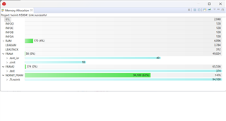
I am trying to use a msp430FR6007 in an application having two large arrays and three smaller ones.  The large arrays are 63,000 bytes and 31,000 bytes.  The smaller ones are a few hundred bytes each.  The array must be nonvolatile and are located with the pragma NOINIT statement.


I had thought to locate them above 0x10000 although their location does not really matter.  Nonvolatile NOINIT does matter, however.


I seem to be able to compile the program (a test version) but apparently cannot link it getting the errors “#10015-D output file  cannot be loaded, etc.” and "#17003-D  relocation from function "main" to symbol, etc.” for each array and variables associated with each array.


I have looked at the ti site and the forums but am not making progress.  I think I do not understand how to set up the link command file and do not know how to achieve the result I desire.


How do I manipulate arrays such as I need to use and do so without violating address restrictions (I presume there must be some but I don’t know what they are!)?  How do I set up the project and linker file to achieve my desired result?


Any help will be greatly appreciated.  Are there any documents that would help?  I've found and read the basic fram documents as well as several posts of the forum.


Regards

Bob Scott

bobscott@jamesports.com

214.673.1439

4/22/23

  • In the default linker .cmd file the TI.noinit section is placed in RAM, which is probably what is causing your build errors.

    Ordinarily it would suffice to move the "TI.noinit : {} >RAM" line up into GROUP(READ_WRITE_MEMORY) after TI.persistent (and remove ">RAM"). With that configuration, the linker would configure the MPU for you. In your case though, your arrays are so large that I expect that would push the text._isr section (which needs to be in low memory) up out of low FRAM.

    There are some more "elegant" (but complex) ways to do this, but I think the simplest would be to carve out the top of the FRAM2 memory region into a new MEMORY region (let's call it NOINIT_FRAM), sized to fit all your arrays and aligned on a 1KB (0x400) boundary (for the MPU). I can't seem to find a copy of lnk_msp430fr6007.cmd, but I think it might look something like:

     FRAM2          : origin = 0x10000,length = 0x20000
     NOINIT_FRAM    : origin = 0x30000,length = 0x14000

    Then you could just change the TI.noinit assignment to "TI.noinit : {} >NOINIT_FRAM". 

    You would then have to manually configure the MPU ("Build Settings->General->MPU[tab]") to make that region RW, since the automatic configuration doesn't really cover this case. 

    I haven't tried this, but I think it should work. I tried it and it seems to work.

    Somewhat related: Since I expect you want these arrays to survive new code downloads, you should probably set the Erase settings ("Properties->Debug->MSP430 Flash Settings->Erase Options") to "Replace written, retain unwritten" -- or maybe "necessary segments only", I forget.

    [Edit: fixed typo; minor clarification; fixed .cmd file name] [More edit: I tried it on an FR5994, which has a similar memory map.]

  • I will try to play with this.  I have also made a shell program which demonstrates the problem.  Attach find main.c, main.h and  the lnk_msp430fr6007.cmd file.  I appreciate all the help I can get.

    main.c
    
    #include <msp430.h> 
    #include "msp430fr6007.h"
    #include "main.h"
    #include "stdlib.h"
    #include "string.h"
    
    
    #pragma NOINIT (numtrans)
    int numtrans;  //number of transations
    #pragma NOINIT (transstart)
    int transstart;  //starting transaction address
    #pragma NOINIT (transend)
    int transend;    //ending tranaction address
    #pragma NOINIT (card)
    CARD card[2000];  //cards to b used
    #pragma NOINIT (numcards)
    int numcards;
    #pragma NOINIT (hose)
    HOSE hose[8];   //hose file
    #pragma NOINIT (config)
    CONFIG  config; //local configuration
    #pragma NOINIT (combfr)
    char    combfr[COMBFRSIZE];   //transmit/receive buffer for large files
    #pragma NOINIT (BadMsgCnt)
    char    BadMsgCnt;
    #pragma NOINIT (pt1)
    char    pt1[21];    //first prompt a char string usually SWIPE OR ENTER CARD
    #pragma NOINIT (pt2)
    char    pt2[21];    //has to be 20 char plus one for null
    #pragma NOINIT (pt3)
    char    pt3[21];
    #pragma NOINIT (pt4)
    char    pt4[21];
    #pragma NOINIT (pt5)
    char    pt5[21];
    #pragma NOINIT (pt6)
    char    pt6[21];
    #pragma NOINIT (pt7)
    char    pt7[21];
    #pragma NOINIT (pt8)
    char    pt8[21];
    #pragma NOINIT (pt9)
    char    pt9[21];
    #pragma NOINIT (pt10)
    char    pt10[21];
    
    
    //variables for ram
    int msecs;
    int msecs5;
    int secmsec;
    char myAddress[2];
    
    /**
     * main.c
     */
    void main(void)
    {
    	
        WDTCTL = WDTPW | WDTHOLD;   // stop watchdog timer
        _DINT();  //TURN OFF INTERRUPTS
    
    //THIS NEXT SECTION IS JUST TEST STUFF
        int modvalue = 2;
        numtrans = modvalue;
        transstart = 0;
        transend = 2;
        card[0].num = 3;
        numcards = 2;
        hose[2].num = 2;
        combfr[0]= 0x02;
    //END TEST STUFF
    
        init_micro();  //init things
    
        if (CEINT == 0)
        {
            __asm(" NOP ") ;
            //display message "POWER FAIL INOPERATIVE"
        }else
        {
            CEINT = 0x0110;  //turn on power fail int
        }
        _EINT();  //turn on interrupts but note that Swipe and  interrupts are not enabled locally
                  //so, at this point the only things on are the power fail, 1 ms timer, and uart interrupts
    
    	return 0;
    }
    
    /*===========================================================================
    *
    * Function: TimerA0_int
    *
    * Desc:     This INTERRUPT polls the offhook switches every msec
    *               has a debounce routine and sets offhook status for each side
    *
    *               Could also poll pulser at offhook = true for each side
    *               This would reduce number of interrupts
    *
    * Parms:    none.
    * Returns:  none.
    *
    ---------------------------------------------------------------------------*/
    
    #pragma vector=TIMER0_A0_VECTOR
    __interrupt void TIMER0_A0_int(void)
    
    {
    
      ++msecs;                // this interupt occurs every millisec increments counter each time
       ++msecs5;               // can use this as another polling timer
       ++secmsec;
    
    }
    
    
    /*===========================================================================
    *
    * Function: init_micro
    *
    * Desc:   Setup micro inputs and outputs, serial channels, clocks, A/Ds and interupts
    *
    * Parms:    none.
    * Returns:  none.
    *
    ---------------------------------------------------------------------------*/
    void    init_micro(void)
    {
        WDTCTL = WDTPW + WDTHOLD;       // Stop WDT interrupt
           PMMCTL0 = 0XA540;  //UNLOCK PMM REGS
    
           PM5CTL0 = ~LOCKLPM5;  //turn on io port config ability
           UCA0CTLW0 = 0X00E1;              // hold in reset to setup
    
     /*      UCA1BRW  = 0x0004;          // 57,600 based on 4 MHz clock
           UCA1MCTLW = 0x5551;              // 57,600 based on 4 MHz clock
    
                // init main registors  do port selection first for hfxtl*/
           FRCTL0 = 0xA510;  //setwrite protect for FR memory
    
           // Set up port J  ok
    
       PJSEL0 = 0xC0;          // BITS 4 & 5 ARE IO
       PJSEL1 = 0x00;
       PJDIR = 0x30;           // all outputs (not used)
       PJOUT = 0x00;           // initial output state all low


           //CLOCK  ok
    
           CSCTL0 = 0xA500;  //set password to change clock registers
    
           CSCTL4 = 0xC001;  //HF ON, HIGH DRIVE, OTHE OSCS OFF
    
           CSCTL2 = 0x0055;  //HF USED FOR ALL CLOCKS
    
           CSCTL3 = 0x0000;  //DIV BY 1 ON ALL CLOCKS
    
           int m = 0;  //wait for clock to stabilize
           while (m < 1000)
           {
               m++;
           }
    
           CSCTL5 &= ~HFXTOFFG;  // RESET FAULTS
    
           do
            {
              CSCTL5 &= ~(LFXTOFFG | HFXTOFFG);       // Clear XT1 and XT2 fault flag
              SFRIFG1 &= ~OFIFG;
            }while (CSCTL5 & HFXTOFFG);                   // Test oscillator fault flag
    
                // init io ports
    
           P1SEL0 = 0x0D;
           P1SEL1 = 0x01;
            P1DIR = 0x20 ;   //**++ for testing only, P1 bit 1 is an output for time testing
    
        //++  need int now    P1IE  = 0x00;           // initial interrupts disabled (offhook setup for polling 1 msec)
            P1IES  = CLS_ | CRRCL ;        // edge seLect  cls & rcl_ neg, crrcl pos, kbint pos
            P8OUT &= ~TEST3;
            P2OUT = 0;
            P1OUT = 0x00;           // initial output state all low
    
            P1IFG = 0;  //TRYING TO CLEAR INT FLAGS
            P1IE = 0x00;  //kb int and cls*  no ints to start  only later
    
                // Set up port 2  ok
    
            P2SEL0 = 0x00;          // all pins are I/O
            P2SEL1 = 0x00;
            P2DIR = 0xFF;           // all outputs
            P2IE  = 0x00;           // interrupts disabled
            P2OUT = 0x00;           // initial output state
    
                // Set up port 3  ok
    
            P3SEL0 = 0x00;
            P3SEL1 = 0x00;
            P3DIR = 0xFF;
            P3OUT = 0x00;           // initial output state all low
    
    
                // Set up port 4  ok
    
            P4SEL0 = 0x18;           // all pins are I/O xcept bit 3 - 4  uart
            P4SEL1 = 0x00;
            P4DIR = 0xEF;           // bit 4 is rxd
            P4OUT = 0x4B;
    
                // port 5  OK
    
            P5DIR = 0xF0;
            P5SEL0 = 0x00;
            P5SEL1 = 0x30;
            P5OUT = 0x00;
    
                // PORT 6  OK
    
            P6DIR = 0x0F;
            P6SEL1 = 0x00;
            P6SEL0 = 0x00;
            P6OUT = 0x00;
    
                // PORT 7  ok
    
            P7DIR = 0xFF;
            P7SEL1 = 0x00;
            P7SEL0 = 0x03;
            P7OUT = 0x00;
    
               // PORT 8  ok
    
            P8DIR = 0xFF;
            P8SEL1 = 0x00;
            P8SEL0 = 0x60;
            P8OUT = 0x60;
    
                //port 9  ok
            P9DIR = 0x00;
            P9SEL1 = 0x00;
            P9SEL0 = 0x00;
            P9OUT = 0x00;
    
    
            // init uarts RS485  ok
    
            //UCTL0 = 0x01;
            UCA0CTLW0 = 0X00E1;              // hold in reset to setup
            unsigned char speed = P9IN & (SPEED0 | SPEED1);
    
            switch (speed)
            {
            case 0:  //19.2 kbs
                UCA0BRW = 0x01A;
                UCA0MCTLW = 0xB601;
                break;
    
            case 1:  //38.4 kbs
                UCA0BRW = 0x00D;
                UCA0MCTLW = 0x8401;
                break;
    
            case 2:  //57.6 KBS
                UCA0BRW = 0x008;
                UCA0MCTLW = 0xF7A1;
                break;
    
            case 3:  //115.2 KBS
                UCA0BRW = 0x004;
                UCA0MCTLW = 0x5551;
                break;
    
            }
    
            UCA0CTLW0 = 0X00E0;                 // Initialize USART0 state machine (~SWRST) release reset
            UCA0IE = UCRXIE;                  // Enable usart RX interrupt (ONLY rx)
    
    
                // init timers ok
    
            TA0CTL   = 0x0212;            // SMCLK, count up to TACCR0 (CCR0), clear timer, enable interrupt
            TA0CCTL0 = 0x0010;  //enable compare int
            TA0CCR0  = 0x1F40;          // 1 msec interrupt   8000 BASE 10
            TA0CCTL1 = 0;
            TA0CCTL2 = 0;
            TA0R = 0x0001 ; //  start timer
    
    
        //++ Set up comparator
        CECTL0 = 0x0080;  // + input ch 0 and - input VREF
        CECTL1 = 0x050C ;  //++  comp on, normal mode, output filtered, falling edge int
        CEINT = 0x0000;  // clear pending int flags
        CECTL2 = 0x0424 ;  //++  Vcc to ladder - 60% res ladder
        //CEINT = 0x0100 ;  // int on
    
        //get address in ascii
    
         unsigned char   addressRaw = P5IN & ADMASK;
         addressRaw++; //switcges are zero based but address is 1 based
         if (addressRaw >= 0x0A)
         {
             myAddress[0] = (addressRaw - 0x0A) | 0x30;  //generate ls address char
             myAddress[1] = 0x31;  //gen ms address char
         }else
         {
             myAddress[0] = addressRaw | 0x30;  //generate ls address char
             myAddress[1] = 0x30;  // ms address char
         }
    }
    
    /*===========================================================================
    *
    * Function: COMP_E_int
    *
    * Desc:    POWER FAIL interrupt
    *
    * ++NOTE:  This interrupt occurs when power drops below 9.1 volts and causes storge of volatile data
    *           before a reset occurs.  Hold up time for this function is about 8 ms.  Logic stays in
    *           this routine until a hardware reset occurs or the power comes back into tolerance for
    *           a time period of about 5 secs.
    *
    * Parms:    none.
    * Returns:  none.
    *
    ---------------------------------------------------------------------------*/
    #pragma vector=COMP_E_VECTOR
    __interrupt void COMP_E_int(void)
    {
        ULONG counter = 0;
        _DINT();
    
        P4OUT = SETPWRFAIL; //turn off leds to save power
        //if any stores are needed, do them here
    
        while (1)
        {
            while (COMPARE == 0)
            {
                counter = 0;  //power bad so clear delay counter
            }
            while (COMPARE > 0)
            {
                counter++;  //power good must be good for about 5 secs before restart
                if (counter > APPRX5SEC)
                {
                    WDTCTL = 0x0000;  //bad write to WDT causes power on reset
                }
            }
        }
        //while loop for routine  only exits with power on clear
        // while loop while power bad wait forever if necessary
        //then if power good while loop forapprx 5 secs if power goes bad
        //   then restart the whole process again
    
    }


    main.h
    
    /*
     * main.h
     *
     *  Created on: May 15, 2022
     *      Author: bobsc
     */
    
    
    #ifndef MAIN_H_
    #define MAIN_H_
    
    
    typedef unsigned int  WORD;             //LSH 2-byte Integer 0 - 65,535
    typedef unsigned long ULONG;            //LSH 4-byte Interger 0 - 2 billion
    
    //structs
    
    typedef struct {
        unsigned char    hrs;
        unsigned char    mins;
        unsigned char    secs;
    } TIME;
    
    typedef struct
    {
        long long int    card;    //16 digit card number
        char    hsid;       //Hose / Prod ID
        char    pin[4];     //PIN
        long int    vol;     //volume
        long int    limit;  // max delivery allowed
        char    status[2];     //2 status char
        char    p2[4];      //4 digit prompt 2 reponse
        char    p3[4];      // prompt3
        char    p4[4];
        char    p5[4];
        char    p6[17];     //p6 response 34 digits or 17 alpha chars
    } TRANSACTION;
    
    typedef struct
    {
        long long int    num;     //card number
        int     pin;     //PIN
        char    exp[2];     //expiration  0 if none
        long int    vollimit;    //volue limit each sale
        char    prodid;     //Product id
        char    p2;         //p2  prompt number  0 if not used
        char    p3;
        char    p4;
        char    p5;
        char    p6;         //also used for VIN can be alpha
    } CARD;
    
    typedef struct
    {
        char    num;        //hose number
        long int    vollimit;   //volume limit each sale 0 no limit
        char    prodid;     //product id
        char    status[2];  //status bytes
        char    units;      //unit per tick
        char    pto;        //pulser timeout in minutes
        char    ohto;       //off hook time out in minutes
    } HOSE;
    
    typedef struct
    {
        char    trname[8];  //Transaction level name
        char    trpass[8];  //Tranaction level password
        char    adname[8];  //admin level name
        char    adpass[8];  //admin level password
        char    tkname[8];  //tech level name
        char    tkpass[8];  //tech level password
        char    site[20];   //site name
        char    addr[40];   //site address
        char    city[60];   //city, state, zip
        int     first4;  //four digit ok to run  use password list
        int     second4; //second four digit
        int     third4;
        int     fourth4;
    } CONFIG;


    // constants
    
    //ASCII CONTROL CHAR
    #define     NULL            0x00
    #define     SOH             0x01
    #define     STX             0x02
    #define     ETX             0x03
    #define     EOT             0x04
    #define     ENQ             0x05
    #define     ACK             0x06
    #define     CR              0x0D
    #define     LF              0x0A
    #define     DLE             0x10
    #define     DC1             0x11
    #define     NAK             0x15
    #define     ETB             0x17
    #define     ENDSEN          0x3F //"?"
    #define     STARTSEN        0X3B  //";"
    #define     FIELDSEP        0x3D  //"="
    #define     DEL             0x7F
    #define     CRBUFSIZE       50
    #define     KBBUFSIZE       100
    #define     COMBFRSIZE      65000
    
    //OTHER CONSTS
    
    #define     KBINMASK        0xF0
    #define     KBOUTMASK       0x0F
    #define     KBPROPDELAY     20  //about 5usec
    #define     CRMASK          0x0F
    #define     BF              0x80  //display busy flag
    #define     ADMASK          0x0F  //for reading address bits
    #define     MASKINT         0x0F  //for converting from ascii to int
    #define     txBfr485Len     72    //size of 485 tx buffer
    #define     rxBfr485Len     72    //size of 485 rx buffer
    #define     DispMax         32    //max size of display buffer
    #define     DispSize        16    //max size of display
    #define     COMMTO          300 //Timeout for loss of communications - 30 sec in 0.1 sec ticks
    #define     APPRX5SEC       0x00100000 //++ rough guess at what counter ought
                                                       //++to be  for recovery from fast power fail
                                                       //++ apprx 5 secs
    
    //some macros
    
    #define     SETPWRFAIL      P4OUT & !PWRFAIL_  //power fail is active low
    #define     RSPWRFAIL       P4OUT & PWRFAIL_
    #define     COMPARE         CECTL1 & CEOUT    //int value and will equal 1 if power good, else bad
    
    //indexes  location in tx and rx buffers
    #define     AdIdx           0x01
    #define     CmdIdx          0x04
    #define     LenIdx          0x05
    #define     DataIdx         0x09
    #define     DvcIdx          0x11
    #define     ModeIdx         0x08
    //#define     StatEOTIdx      5
    
    //#define     MSG0[16]          " ENTER/SWIPE ID "
    
    // flags
    //ready flags
    
    #define     KBDATA          0x01
    #define     KBREADY         0x02
    #define     CRDATA          0x04
    #define     CRREADY         0X08
    #define     PCRLOW          0x10
    #define     PCRHI           0x20
    
    //rx buffer flags
    
    #define     ETBrxd          0x01
    #define     ETXrxd          0x02
    #define     NUMrxdNoEOT     0x04
    #define     EOTrxd          0x08
    #define     LoggedIn        0x10
    #define     UART0_RX        0x20
    
    //CPU PORT DEFINES
    
    //PORT 1
    #define     POWERIN         0x01    //P1-0
    #define     CLS_            0x02
    #define     CRTXD           0x04
    #define     CRRXD           0x08
    #define     CRRTD           0x08
    #define     CRCTS           0x10
    #define     CRRCL           0x10
    #define     TEST7           0x20
    #define     DCD             0x40
    #define     KBINT           0x80
    
    //port2
    #define     C0              0x01  //pulsers
    #define     C1              0x02
    #define     C2              0x04
    #define     C3              0x08
    #define     C4              0x10
    #define     C5              0x20
    #define     TEST6           0x40
    #define     TEST5           0x80
    
    //PORT3
    #define     D0              0x01  //databus
    #define     D1              0x02
    #define     D2              0x04
    #define     D3              0x08
    #define     D4              0x10
    #define     D5              0x20
    #define     D6              0x40
    #define     D7              0x80
    
    //port4
    #define     LCDEN_          0x01
    #define     RS_             0x02
    #define     LCDWrR          0x04
    #define     TXD             0x08
    #define     RXD             0x10
    #define     TXrRX           0x20
    #define     PWRFAIL_        0x40
    #define     BEEP            0x80
    
    //port5
    #define     R0              0x01  //RELAYS
    #define     R1              0x02
    #define     R2              0x04
    #define     RTCCSL          0x08
    #define     RTCSDA          0x10
    #define     R3              0x20
    #define     R4              0x40
    #define     R5              0x80
    
    //port6
    #define     KBO0            0x01  //KEYBOARD INS/OUTS
    #define     KBO1            0x02
    #define     KBO2            0x04
    #define     KBO3            0x08
    #define     KBI0            0x10
    #define     KBI1            0x20
    #define     KBI2            0x40
    #define     KBI3            0x80
    
    //port7
    #define     PTXD            0x01  //ptr serial
    #define     PRXD            0x02
    #define     PTXrRX          0x04
    #define     TEST4           0x08
    #define     P0              0x10  //pump handles
    #define     P1              0x20
    #define     P2              0x40
    #define     P3              0x80
    
    //port8
    #define     P4              0x01
    #define     P5              0x02
    #define     TEST3           0x04
    #define     TEST2           0x08
    #define     CRRTS_          0x10
    #define     MSDA            0x20
    #define     MSCL            0x40
    #define     TEST8           0x80
    
    //port9
    #define     SPEED0          0x01  //SWITCHES  speed bit0
    #define     SPEED1          0x02    //speed bit1
    #define     RS485           0x04  //RS485 or RS232 (low)
    #define     SWIPE_          0x08  //low for swipe reader, high for RS232
    
    //port J
    #define     TDO             0x01  /jtag pins
    #define     TDI             0x02
    #define     TMS             0x04
    #define     TCK             0x08
    #define     TEST1           0x10  //test pins (unused)
    #define     TEST9           0x20
    #define     HFXIN           0x40  //8mhz xytl
    #define     HFXOUT          0x80
    
    // key codes defined
    
    #define     KBCLR           0xBE  //pins 7-3 shorted
    #define     KB0             0xBD  //pins 7-4
    #define     KBENT           0xBB  //pins 7-5
    #define     KB1             0x7E  //pins 8-3
    #define     KB2             0x7D  //pins 8-4
    #define     KB3             0x7B  //pins 8-5
    #define     KB4             0xDE  //pins 2-3
    #define     KB5             0xDD  //pins 2-4
    #define     KB6             0xDB  //pins 2-5
    #define     KB7             0xEE  //pins 1-3
    #define     KB8             0xED  //pins 1-4
    #define     KB9             0xEB  //pins 1-5
    
    //routines
    
    void    main(void);
    void    init_micro(void);
    
    
    #endif /* MAIN_H_ */
    
    main.c
    
    430.h> 
    #include "msp430fr6007.h"
    #include "main.h"
    #include "stdlib.h"
    #include "string.h"
    
    
    #pragma NOINIT (numtrans)
    int numtrans;  //number of transations
    #pragma NOINIT (transstart)
    int transstart;  //starting transaction address
    #pragma NOINIT (transend)
    int transend;    //ending tranaction address
    #pragma NOINIT (card)
    CARD card[2000];  //cards to b used
    #pragma NOINIT (numcards)
    int numcards;
    #pragma NOINIT (hose)
    HOSE hose[8];   //hose file
    #pragma NOINIT (config)
    CONFIG  config; //local configuration
    #pragma NOINIT (combfr)
    char    combfr[COMBFRSIZE];   //transmit/receive buffer for large files
    #pragma NOINIT (BadMsgCnt)
    char    BadMsgCnt;
    #pragma NOINIT (pt1)
    char    pt1[21];    //first prompt a char string usually SWIPE OR ENTER CARD
    #pragma NOINIT (pt2)
    char    pt2[21];    //has to be 20 char plus one for null
    #pragma NOINIT (pt3)
    char    pt3[21];
    #pragma NOINIT (pt4)
    char    pt4[21];
    #pragma NOINIT (pt5)
    char    pt5[21];
    #pragma NOINIT (pt6)
    char    pt6[21];
    #pragma NOINIT (pt7)
    char    pt7[21];
    #pragma NOINIT (pt8)
    char    pt8[21];
    #pragma NOINIT (pt9)
    char    pt9[21];
    #pragma NOINIT (pt10)
    char    pt10[21];
    
    
    //variables for ram
    int msecs;
    int msecs5;
    int secmsec;
    char myAddress[2];
    
    /**
     * main.c
     */
    void main(void)
    {
    	
        WDTCTL = WDTPW | WDTHOLD;   // stop watchdog timer
        _DINT();  //TURN OFF INTERRUPTS
    
    //THIS NEXT SECTION IS JUST TEST STUFF
        int modvalue = 2;
        numtrans = modvalue;
        transstart = 0;
        transend = 2;
        card[0].num = 3;
        numcards = 2;
        hose[2].num = 2;
        combfr[0]= 0x02;
    //END TEST STUFF
    
        init_micro();  //init things
    
        if (CEINT == 0)
        {
            __asm(" NOP ") ;
            //display message "POWER FAIL INOPERATIVE"
        }else
        {
            CEINT = 0x0110;  //turn on power fail int
        }
        _EINT();  //turn on interrupts but note that Swipe and  interrupts are not enabled locally
                  //so, at this point the only things on are the power fail, 1 ms timer, and uart interrupts
    
    	return 0;
    }
    
    /*===========================================================================
    *
    * Function: TimerA0_int
    *
    * Desc:     This INTERRUPT polls the offhook switches every msec
    *               has a debounce routine and sets offhook status for each side
    *
    *               Could also poll pulser at offhook = true for each side
    *               This would reduce number of interrupts
    *
    * Parms:    none.
    * Returns:  none.
    *
    ---------------------------------------------------------------------------*/
    
    #pragma vector=TIMER0_A0_VECTOR
    __interrupt void TIMER0_A0_int(void)
    
    {
    
      ++msecs;                // this interupt occurs every millisec increments counter each time
       ++msecs5;               // can use this as another polling timer
       ++secmsec;
    
    }
    
    
    /*===========================================================================
    *
    * Function: init_micro
    *
    * Desc:   Setup micro inputs and outputs, serial channels, clocks, A/Ds and interupts
    *
    * Parms:    none.
    * Returns:  none.
    *
    ---------------------------------------------------------------------------*/
    void    init_micro(void)
    {
        WDTCTL = WDTPW + WDTHOLD;       // Stop WDT interrupt
           PMMCTL0 = 0XA540;  //UNLOCK PMM REGS
    
           PM5CTL0 = ~LOCKLPM5;  //turn on io port config ability
           UCA0CTLW0 = 0X00E1;              // hold in reset to setup
    
     /*      UCA1BRW  = 0x0004;          // 57,600 based on 4 MHz clock
           UCA1MCTLW = 0x5551;              // 57,600 based on 4 MHz clock
    
                // init main registors  do port selection first for hfxtl*/
           FRCTL0 = 0xA510;  //setwrite protect for FR memory
    
           // Set up port J  ok
    
       PJSEL0 = 0xC0;          // BITS 4 & 5 ARE IO
       PJSEL1 = 0x00;
       PJDIR = 0x30;           // all outputs (not used)
       PJOUT = 0x00;           // initial output state all low


           //CLOCK  ok
    
           CSCTL0 = 0xA500;  //set password to change clock registers
    
           CSCTL4 = 0xC001;  //HF ON, HIGH DRIVE, OTHE OSCS OFF
    
           CSCTL2 = 0x0055;  //HF USED FOR ALL CLOCKS
    
           CSCTL3 = 0x0000;  //DIV BY 1 ON ALL CLOCKS
    
           int m = 0;  //wait for clock to stabilize
           while (m < 1000)
           {
               m++;
           }
    
           CSCTL5 &= ~HFXTOFFG;  // RESET FAULTS
    
           do
            {
              CSCTL5 &= ~(LFXTOFFG | HFXTOFFG);       // Clear XT1 and XT2 fault flag
              SFRIFG1 &= ~OFIFG;
            }while (CSCTL5 & HFXTOFFG);                   // Test oscillator fault flag
    
                // init io ports
    
           P1SEL0 = 0x0D;
           P1SEL1 = 0x01;
            P1DIR = 0x20 ;   //**++ for testing only, P1 bit 1 is an output for time testing
    
        //++  need int now    P1IE  = 0x00;           // initial interrupts disabled (offhook setup for polling 1 msec)
            P1IES  = CLS_ | CRRCL ;        // edge seLect  cls & rcl_ neg, crrcl pos, kbint pos
            P8OUT &= ~TEST3;
            P2OUT = 0;
            P1OUT = 0x00;           // initial output state all low
    
            P1IFG = 0;  //TRYING TO CLEAR INT FLAGS
            P1IE = 0x00;  //kb int and cls*  no ints to start  only later
    
                // Set up port 2  ok
    
            P2SEL0 = 0x00;          // all pins are I/O
            P2SEL1 = 0x00;
            P2DIR = 0xFF;           // all outputs
            P2IE  = 0x00;           // interrupts disabled
            P2OUT = 0x00;           // initial output state
    
                // Set up port 3  ok
    
            P3SEL0 = 0x00;
            P3SEL1 = 0x00;
            P3DIR = 0xFF;
            P3OUT = 0x00;           // initial output state all low
    
    
                // Set up port 4  ok
    
            P4SEL0 = 0x18;           // all pins are I/O xcept bit 3 - 4  uart
            P4SEL1 = 0x00;
            P4DIR = 0xEF;           // bit 4 is rxd
            P4OUT = 0x4B;
    
                // port 5  OK
    
            P5DIR = 0xF0;
            P5SEL0 = 0x00;
            P5SEL1 = 0x30;
            P5OUT = 0x00;
    
                // PORT 6  OK
    
            P6DIR = 0x0F;
            P6SEL1 = 0x00;
            P6SEL0 = 0x00;
            P6OUT = 0x00;
    
                // PORT 7  ok
    
            P7DIR = 0xFF;
            P7SEL1 = 0x00;
            P7SEL0 = 0x03;
            P7OUT = 0x00;
    
               // PORT 8  ok
    
            P8DIR = 0xFF;
            P8SEL1 = 0x00;
            P8SEL0 = 0x60;
            P8OUT = 0x60;
    
                //port 9  ok
            P9DIR = 0x00;
            P9SEL1 = 0x00;
            P9SEL0 = 0x00;
            P9OUT = 0x00;
    
    
            // init uarts RS485  ok
    
            //UCTL0 = 0x01;
            UCA0CTLW0 = 0X00E1;              // hold in reset to setup
            unsigned char speed = P9IN & (SPEED0 | SPEED1);
    
            switch (speed)
            {
            case 0:  //19.2 kbs
                UCA0BRW = 0x01A;
                UCA0MCTLW = 0xB601;
                break;
    
            case 1:  //38.4 kbs
                UCA0BRW = 0x00D;
                UCA0MCTLW = 0x8401;
                break;
    
            case 2:  //57.6 KBS
                UCA0BRW = 0x008;
                UCA0MCTLW = 0xF7A1;
                break;
    
            case 3:  //115.2 KBS
                UCA0BRW = 0x004;
                UCA0MCTLW = 0x5551;
                break;
    
            }
    
            UCA0CTLW0 = 0X00E0;                 // Initialize USART0 state machine (~SWRST) release reset
            UCA0IE = UCRXIE;                  // Enable usart RX interrupt (ONLY rx)
    
    
                // init timers ok
    
            TA0CTL   = 0x0212;            // SMCLK, count up to TACCR0 (CCR0), clear timer, enable interrupt
            TA0CCTL0 = 0x0010;  //enable compare int
            TA0CCR0  = 0x1F40;          // 1 msec interrupt   8000 BASE 10
            TA0CCTL1 = 0;
            TA0CCTL2 = 0;
            TA0R = 0x0001 ; //  start timer
    
    
        //++ Set up comparator
        CECTL0 = 0x0080;  // + input ch 0 and - input VREF
        CECTL1 = 0x050C ;  //++  comp on, normal mode, output filtered, falling edge int
        CEINT = 0x0000;  // clear pending int flags
        CECTL2 = 0x0424 ;  //++  Vcc to ladder - 60% res ladder
        //CEINT = 0x0100 ;  // int on
    
        //get address in ascii
    
         unsigned char   addressRaw = P5IN & ADMASK;
         addressRaw++; //switcges are zero based but address is 1 based
         if (addressRaw >= 0x0A)
         {
             myAddress[0] = (addressRaw - 0x0A) | 0x30;  //generate ls address char
             myAddress[1] = 0x31;  //gen ms address char
         }else
         {
             myAddress[0] = addressRaw | 0x30;  //generate ls address char
             myAddress[1] = 0x30;  // ms address char
         }
    }
    
    /*===========================================================================
    *
    * Function: COMP_E_int
    *
    * Desc:    POWER FAIL interrupt
    *
    * ++NOTE:  This interrupt occurs when power drops below 9.1 volts and causes storge of volatile data
    *           before a reset occurs.  Hold up time for this function is about 8 ms.  Logic stays in
    *           this routine until a hardware reset occurs or the power comes back into tolerance for
    *           a time period of about 5 secs.
    *
    * Parms:    none.
    * Returns:  none.
    *
    ---------------------------------------------------------------------------*/
    #pragma vector=COMP_E_VECTOR
    __interrupt void COMP_E_int(void)
    {
        ULONG counter = 0;
        _DINT();
    
        P4OUT = SETPWRFAIL; //turn off leds to save power
        //if any stores are needed, do them here
    
        while (1)
        {
            while (COMPARE == 0)
            {
                counter = 0;  //power bad so clear delay counter
            }
            while (COMPARE > 0)
            {
                counter++;  //power good must be good for about 5 secs before restart
                if (counter > APPRX5SEC)
                {
                    WDTCTL = 0x0000;  //bad write to WDT causes power on reset
                }
            }
        }
        //while loop for routine  only exits with power on clear
        // while loop while power bad wait forever if necessary
        //then if power good while loop forapprx 5 secs if power goes bad
        //   then restart the whole process again
    
    }lnk_msp430fr6007.cmd
    
    /******************************************************************************
    *
    * Copyright (C) 2012 - 2021 Texas Instruments Incorporated - http://www.ti.com/
    *
    * Redistribution and use in source and binary forms, with or without
    * modification, are permitted provided that the following conditions
    * are met:
    *
    *  Redistributions of source code must retain the above copyright
    *  notice, this list of conditions and the following disclaimer.
    *
    *  Redistributions in binary form must reproduce the above copyright
    *  notice, this list of conditions and the following disclaimer in the
    *  documentation and/or other materials provided with the
    *  distribution.
    *
    *  Neither the name of Texas Instruments Incorporated nor the names of
    *  its contributors may be used to endorse or promote products derived
    *  from this software without specific prior written permission.
    *
    * THIS SOFTWARE IS PROVIDED BY THE COPYRIGHT HOLDERS AND CONTRIBUTORS
    * "AS IS" AND ANY EXPRESS OR IMPLIED WARRANTIES, INCLUDING, BUT NOT
    * LIMITED TO, THE IMPLIED WARRANTIES OF MERCHANTABILITY AND FITNESS FOR
    * A PARTICULAR PURPOSE ARE DISCLAIMED. IN NO EVENT SHALL THE COPYRIGHT
    * OWNER OR CONTRIBUTORS BE LIABLE FOR ANY DIRECT, INDIRECT, INCIDENTAL,
    * SPECIAL, EXEMPLARY, OR CONSEQUENTIAL DAMAGES (INCLUDING, BUT NOT
    * LIMITED TO, PROCUREMENT OF SUBSTITUTE GOODS OR SERVICES; LOSS OF USE,
    * DATA, OR PROFITS; OR BUSINESS INTERRUPTION) HOWEVER CAUSED AND ON ANY
    * THEORY OF LIABILITY, WHETHER IN CONTRACT, STRICT LIABILITY, OR TORT
    * (INCLUDING NEGLIGENCE OR OTHERWISE) ARISING IN ANY WAY OUT OF THE USE
    * OF THIS SOFTWARE, EVEN IF ADVISED OF THE POSSIBILITY OF SUCH DAMAGE.
    *
    * Default linker command file for Texas Instruments MSP430FR6007
    *
    *****************************************************************************/
    
    /******************************************************************************/
    /*                                                                            */
    /*   Usage:  lnk430 <obj files...>    -o <out file> -m <map file> lnk.cmd     */
    /*           cl430  <src files...> -z -o <out file> -m <map file> lnk.cmd     */
    /*                                                                            */
    /*----------------------------------------------------------------------------*/
    /* These linker options are for command line linking only.  For IDE linking,  */
    /* you should set your linker options in Project Properties                   */
    /* -c                                               LINK USING C CONVENTIONS  */
    /* -stack  0x0100                                   SOFTWARE STACK SIZE       */
    /* -heap   0x0100                                   HEAP AREA SIZE            */
    /*                                                                            */
    /*----------------------------------------------------------------------------*/
    /* 1.213 */
    /*----------------------------------------------------------------------------*/
    
    /****************************************************************************/
    /* SPECIFY THE SYSTEM MEMORY MAP                                            */
    /****************************************************************************/
    
    MEMORY
    {
        TINYRAM                 : origin = 0xA, length = 0x16
        BSL                     : origin = 0x1000, length = 0x800
        CAL_CONF                : origin = 0x1900, length = 0x100
        TLVMEM                  : origin = 0x1A00, length = 0x100
        BOOTROM                 : origin = 0x1B00, length = 0x100
        RAM                     : origin = 0x1C00, length = 0x1000
        FRAM                    : origin = 0x4000, length = 0xBF80
        FRAM2                   : origin = 0x10000,length = 0x33FF8 /* Boundaries changed to fix CPU47 */
        JTAGSIGNATURE           : origin = 0xFF80, length = 0x0004, fill = 0xFFFF
        BSLSIGNATURE            : origin = 0xFF84, length = 0x0004, fill = 0xFFFF
        IPESIGNATURE            : origin = 0xFF88, length = 0x0008, fill = 0xFFFF
        INT00                   : origin = 0xFF90, length = 0x0002
        INT01                   : origin = 0xFF92, length = 0x0002
        INT02                   : origin = 0xFF94, length = 0x0002
        INT03                   : origin = 0xFF96, length = 0x0002
        INT04                   : origin = 0xFF98, length = 0x0002
        INT05                   : origin = 0xFF9A, length = 0x0002
        INT06                   : origin = 0xFF9C, length = 0x0002
        INT07                   : origin = 0xFF9E, length = 0x0002
        INT08                   : origin = 0xFFA0, length = 0x0002
        INT09                   : origin = 0xFFA2, length = 0x0002
        INT10                   : origin = 0xFFA4, length = 0x0002
        INT11                   : origin = 0xFFA6, length = 0x0002
        INT12                   : origin = 0xFFA8, length = 0x0002
        INT13                   : origin = 0xFFAA, length = 0x0002
        INT14                   : origin = 0xFFAC, length = 0x0002
        INT15                   : origin = 0xFFAE, length = 0x0002
        INT16                   : origin = 0xFFB0, length = 0x0002
        INT17                   : origin = 0xFFB2, length = 0x0002
        INT18                   : origin = 0xFFB4, length = 0x0002
        INT19                   : origin = 0xFFB6, length = 0x0002
        INT20                   : origin = 0xFFB8, length = 0x0002
        INT21                   : origin = 0xFFBA, length = 0x0002
        INT22                   : origin = 0xFFBC, length = 0x0002
        INT23                   : origin = 0xFFBE, length = 0x0002
        INT24                   : origin = 0xFFC0, length = 0x0002
        INT25                   : origin = 0xFFC2, length = 0x0002
        INT26                   : origin = 0xFFC4, length = 0x0002
        INT27                   : origin = 0xFFC6, length = 0x0002
        INT28                   : origin = 0xFFC8, length = 0x0002
        INT29                   : origin = 0xFFCA, length = 0x0002
        INT30                   : origin = 0xFFCC, length = 0x0002
        INT31                   : origin = 0xFFCE, length = 0x0002
        INT32                   : origin = 0xFFD0, length = 0x0002
        INT33                   : origin = 0xFFD2, length = 0x0002
        INT34                   : origin = 0xFFD4, length = 0x0002
        INT35                   : origin = 0xFFD6, length = 0x0002
        INT36                   : origin = 0xFFD8, length = 0x0002
        INT37                   : origin = 0xFFDA, length = 0x0002
        INT38                   : origin = 0xFFDC, length = 0x0002
        INT39                   : origin = 0xFFDE, length = 0x0002
        INT40                   : origin = 0xFFE0, length = 0x0002
        INT41                   : origin = 0xFFE2, length = 0x0002
        INT42                   : origin = 0xFFE4, length = 0x0002
        INT43                   : origin = 0xFFE6, length = 0x0002
        INT44                   : origin = 0xFFE8, length = 0x0002
        INT45                   : origin = 0xFFEA, length = 0x0002
        INT46                   : origin = 0xFFEC, length = 0x0002
        INT47                   : origin = 0xFFEE, length = 0x0002
        INT48                   : origin = 0xFFF0, length = 0x0002
        INT49                   : origin = 0xFFF2, length = 0x0002
        INT50                   : origin = 0xFFF4, length = 0x0002
        INT51                   : origin = 0xFFF6, length = 0x0002
        INT52                   : origin = 0xFFF8, length = 0x0002
        INT53                   : origin = 0xFFFA, length = 0x0002
        INT54                   : origin = 0xFFFC, length = 0x0002
        RESET                   : origin = 0xFFFE, length = 0x0002
    }
    
    /****************************************************************************/
    /* Specify the LEA memory map                                               */
    /****************************************************************************/
    
    #define LEASTACK_SIZE   0x138
    
    MEMORY
    {
        LEARAM                  : origin = 0x2C00, length = 0x1000 - LEASTACK_SIZE
        LEASTACK                : origin = 0x3C00 - LEASTACK_SIZE, length = LEASTACK_SIZE
    }
    
    /****************************************************************************/
    /* SPECIFY THE SECTIONS ALLOCATION INTO MEMORY                              */
    /****************************************************************************/
    
    SECTIONS
    {
        GROUP(RW_IPE)
        {
    
            GROUP(READ_WRITE_MEMORY)
            {
    
                .TI.persistent : {}              /* For #pragma persistent            */
                .cio           : {}              /* C I/O Buffer                      */
                .sysmem        : {}              /* Dynamic memory allocation area    */
            } PALIGN(0x0400), RUN_START(fram_rw_start)
    
            GROUP(IPENCAPSULATED_MEMORY)
            {
    
                .ipestruct     : {}              /* IPE Data structure             */
                .ipe           : {}              /* IPE                            */
                .ipe_const     : {}              /* IPE Protected constants        */
                .ipe:_isr      : {}              /* IPE ISRs                       */
            } PALIGN(0x0400), RUN_START(fram_ipe_start) RUN_END(fram_ipe_end) RUN_END(fram_rx_start)
    
        } > 0x4000
    
        .cinit            : {}  > FRAM          /* Initialization tables             */
        .binit            : {}  > FRAM          /* Boot-time Initialization tables   */
        .pinit            : {}  > FRAM          /* C++ Constructor tables            */
        .init_array       : {}  > FRAM          /* C++ Constructor tables            */
        .mspabi.exidx     : {}  > FRAM          /* C++ Constructor tables            */
        .mspabi.extab     : {}  > FRAM          /* C++ Constructor tables            */
        .text:_isr        : {}  > FRAM          /* Code ISRs                         */
    
    #ifndef __LARGE_DATA_MODEL__
        .const            : {} > FRAM           /* Constant data                     */
    #else
        .const            : {} >> FRAM | FRAM2  /* Constant data                     */
    #endif
    
    #ifndef __LARGE_CODE_MODEL__
        .text             : {} > FRAM           /* Code                              */
    #else
        .text             : {} >> FRAM2 | FRAM  /* Code                              */
    #endif
    
        #ifdef __TI_COMPILER_VERSION__
            #if __TI_COMPILER_VERSION__ >= 15009000
                #ifndef __LARGE_CODE_MODEL__
                    .TI.ramfunc : {} load=FRAM, run=RAM, table(BINIT)
                #else
                    .TI.ramfunc : {} load=FRAM | FRAM2, run=RAM, table(BINIT)
                #endif
            #endif
        #endif
    
        .jtagsignature      : {} > JTAGSIGNATURE
        .bslsignature       : {} > BSLSIGNATURE
    
        GROUP(SIGNATURE_SHAREDMEMORY)
        {
            .ipesignature       : {}            /* IPE Signature                     */
            .jtagpassword       : {}            /* JTAG Password                     */
        } > IPESIGNATURE
    
        .bss        : {} > RAM                  /* Global & static vars              */
        .data       : {} > RAM                  /* Global & static vars              */
        .TI.noinit  : {} > FRAM2                  /* For #pragma noinit                */
        .TI.persistent	: {} > FRAM2			//for #pragma persistent
        .stack      : {} > RAM (HIGH)           /* Software system stack             */
    
        .tinyram    : {} > TINYRAM              /* Tiny RAM                          */
    
        .leaRAM      : {} > LEARAM               /* LEA RAM                           */
        .leaStack    : {} > LEASTACK (HIGH)      /* LEA STACK                         */
    
        /* MSP430 interrupt vectors */
    
        .int00       : {}               > INT00
        .int01       : {}               > INT01
        .int02       : {}               > INT02
        .int03       : {}               > INT03
        .int04       : {}               > INT04
        .int05       : {}               > INT05
        .int06       : {}               > INT06
        .int07       : {}               > INT07
        .int08       : {}               > INT08
        .int09       : {}               > INT09
        .int10       : {}               > INT10
        .int11       : {}               > INT11
        .int12       : {}               > INT12
        .int13       : {}               > INT13
        SDHS         : { * ( .int14 ) } > INT14 type = VECT_INIT
        SAPH         : { * ( .int15 ) } > INT15 type = VECT_INIT
        HSPLL        : { * ( .int16 ) } > INT16 type = VECT_INIT
        UUPS         : { * ( .int17 ) } > INT17 type = VECT_INIT
        LEA          : { * ( .int18 ) } > INT18 type = VECT_INIT
        PORT9        : { * ( .int19 ) } > INT19 type = VECT_INIT
        PORT8        : { * ( .int20 ) } > INT20 type = VECT_INIT
        PORT7        : { * ( .int21 ) } > INT21 type = VECT_INIT
        EUSCI_B1     : { * ( .int22 ) } > INT22 type = VECT_INIT
        EUSCI_A3     : { * ( .int23 ) } > INT23 type = VECT_INIT
        EUSCI_A2     : { * ( .int24 ) } > INT24 type = VECT_INIT
        PORT6        : { * ( .int25 ) } > INT25 type = VECT_INIT
        PORT5        : { * ( .int26 ) } > INT26 type = VECT_INIT
        TIMER4_A1    : { * ( .int27 ) } > INT27 type = VECT_INIT
        TIMER4_A0    : { * ( .int28 ) } > INT28 type = VECT_INIT
        AES256       : { * ( .int29 ) } > INT29 type = VECT_INIT
        RTC_C        : { * ( .int30 ) } > INT30 type = VECT_INIT
        LCD_C        : { * ( .int31 ) } > INT31 type = VECT_INIT
        PORT4        : { * ( .int32 ) } > INT32 type = VECT_INIT
        PORT3        : { * ( .int33 ) } > INT33 type = VECT_INIT
        TIMER3_A1    : { * ( .int34 ) } > INT34 type = VECT_INIT
        TIMER3_A0    : { * ( .int35 ) } > INT35 type = VECT_INIT
        PORT2        : { * ( .int36 ) } > INT36 type = VECT_INIT
        TIMER2_A1    : { * ( .int37 ) } > INT37 type = VECT_INIT
        TIMER2_A0    : { * ( .int38 ) } > INT38 type = VECT_INIT
        PORT1        : { * ( .int39 ) } > INT39 type = VECT_INIT
        TIMER1_A1    : { * ( .int40 ) } > INT40 type = VECT_INIT
        TIMER1_A0    : { * ( .int41 ) } > INT41 type = VECT_INIT
        DMA          : { * ( .int42 ) } > INT42 type = VECT_INIT
        EUSCI_A1     : { * ( .int43 ) } > INT43 type = VECT_INIT
        TIMER0_A1    : { * ( .int44 ) } > INT44 type = VECT_INIT
        TIMER0_A0    : { * ( .int45 ) } > INT45 type = VECT_INIT
        ADC12_B      : { * ( .int46 ) } > INT46 type = VECT_INIT
        EUSCI_B0     : { * ( .int47 ) } > INT47 type = VECT_INIT
        EUSCI_A0     : { * ( .int48 ) } > INT48 type = VECT_INIT
        WDT          : { * ( .int49 ) } > INT49 type = VECT_INIT
        TIMER0_B1    : { * ( .int50 ) } > INT50 type = VECT_INIT
        TIMER0_B0    : { * ( .int51 ) } > INT51 type = VECT_INIT
        COMP_E       : { * ( .int52 ) } > INT52 type = VECT_INIT
        UNMI         : { * ( .int53 ) } > INT53 type = VECT_INIT
        SYSNMI       : { * ( .int54 ) } > INT54 type = VECT_INIT
        .reset       : {}               > RESET  /* MSP430 reset vector         */
    
    }
    /****************************************************************************/
    /* MPU/IPE SPECIFIC MEMORY SEGMENT DEFINITONS                               */
    /****************************************************************************/
    
    #ifdef _IPE_ENABLE
        #define IPE_MPUIPLOCK 0x0080
        #define IPE_MPUIPENA 0x0040
        #define IPE_MPUIPPUC 0x0020
    
        // Evaluate settings for the control setting of IP Encapsulation
        #if defined(_IPE_ASSERTPUC1)
            #if defined(_IPE_LOCK ) && (_IPE_ASSERTPUC1 == 0x08))
                fram_ipe_enable_value = (IPE_MPUIPENA | IPE_MPUIPPUC |IPE_MPUIPLOCK);
            #elif defined(_IPE_LOCK )
                fram_ipe_enable_value = (IPE_MPUIPENA | IPE_MPUIPLOCK);
            #elif (_IPE_ASSERTPUC1 == 0x08)
                fram_ipe_enable_value = (IPE_MPUIPENA | IPE_MPUIPPUC);
            #else
                fram_ipe_enable_value = (IPE_MPUIPENA);
            #endif
        #else
            #if defined(_IPE_LOCK )
                fram_ipe_enable_value = (IPE_MPUIPENA | IPE_MPUIPLOCK);
            #else
                fram_ipe_enable_value = (IPE_MPUIPENA);
            #endif
        #endif
    
        // Segment definitions
        #ifdef _IPE_MANUAL                  // For custom sizes selected in the GUI
            fram_ipe_border1 = (_IPE_SEGB1>>4);
            fram_ipe_border2 = (_IPE_SEGB2>>4);
        #else                           // Automated sizes generated by the Linker
            fram_ipe_border2 = fram_ipe_end >> 4;
            fram_ipe_border1 = fram_ipe_start >> 4;
        #endif
    
        fram_ipe_settings_struct_address = Ipe_settingsStruct >> 4;
        fram_ipe_checksum = ~((fram_ipe_enable_value & fram_ipe_border2 & fram_ipe_border1) | (fram_ipe_enable_value & ~fram_ipe_border2 & ~fram_ipe_border1) | (~fram_ipe_enable_value & fram_ipe_border2 & ~fram_ipe_border1) | (~fram_ipe_enable_value & ~fram_ipe_border2 & fram_ipe_border1));
    #endif
    
    #ifdef _MPU_ENABLE
        #define MPUPW (0xA500)    /* MPU Access Password */
        #define MPUENA (0x0001)   /* MPU Enable */
        #define MPULOCK (0x0002)  /* MPU Lock */
        #define MPUSEGIE (0x0010) /* MPU Enable NMI on Segment violation */
    
        __mpu_enable = 1;
        // Segment definitions
        #ifdef _MPU_MANUAL // For custom sizes selected in the GUI
            mpu_segment_border1 = _MPU_SEGB1 >> 4;
            mpu_segment_border2 = _MPU_SEGB2 >> 4;
            mpu_sam_value = (_MPU_SAM0 << 12) | (_MPU_SAM3 << 8) | (_MPU_SAM2 << 4) | _MPU_SAM1;
        #else // Automated sizes generated by Linker
            #ifdef _IPE_ENABLE //if IPE is used in project too
            //seg1 = any read + write persistent variables
            //seg2 = ipe = read + write + execute access
            //seg3 = code, read + execute only
        	       mpu_segment_border1 = fram_ipe_start >> 4;
        	       mpu_segment_border2 = fram_rx_start >> 4;
        	       mpu_sam_value = 0x1573; // Info R, Seg3 RX, Seg2 RWX, Seg1 RW
            #else
        	       mpu_segment_border1 = fram_rx_start >> 4;
        	       mpu_segment_border2 = fram_rx_start >> 4;
        	       mpu_sam_value = 0x1513; // Info R, Seg3 RX, Seg2 R, Seg1 RW
            #endif
        #endif
        #ifdef _MPU_LOCK
            #ifdef _MPU_ENABLE_NMI
                mpu_ctl0_value = MPUPW | MPUENA | MPULOCK | MPUSEGIE;
            #else
                mpu_ctl0_value = MPUPW | MPUENA | MPULOCK;
            #endif
        #else
            #ifdef _MPU_ENABLE_NMI
                mpu_ctl0_value = MPUPW | MPUENA | MPUSEGIE;
            #else
                mpu_ctl0_value = MPUPW | MPUENA;
            #endif
        #endif
    #endif
    
    /****************************************************************************/
    /* INCLUDE PERIPHERALS MEMORY MAP                                           */
    /****************************************************************************/
    
    -l msp430fr6007.cmd


  • In order to put (any) data above 64K, you'll need to set (in "Build Settings->Build->Compiler->Processor Options") data_model=large and near_data=none.

    I suggest you not just put TI.noinit (nor TI.persistent) into FRAM2 like this, since you want to write-enable your data but not other things that might get thrown in there (depending on link ordering). By splitting off a NOINIT_FRAM memory region you can also assure the 1KB (0x400) alignment that the MPU needs.

  • Dear Bruce -

    OK - Looks as though all this works.  At least it doesn't say i can't load the program and the memory map looks good.  However, the Memory Allocation window in CCS shows stuff in FRAM2 and nothing in NOINIT_FRAM although the memory map shows the stuff in the range I defined as NOINIT_FRAM and nothing in FRAM2,  Not sure this means anything.  Does it?

    Other than that, all is well.

    Many many thanx for your help.  Wouldn't have made it without your input!!

    Regards Bob

  • I hadn't used the Memory Allocation window, but when I applied it to my experimental project (for the FR5994) it showed my large TI.noinit in NOINIT_FRAM. I don't know why there's a difference, but I'll suppose that the .map file is authoritative.

    The only real test for the MPU configuration is to try it, but I expect your .map should show mpu_sam_value=0x1bdf and mpu_segment_border2=(base of NOINIT_FRAM)/16. [NOINIT_FRAM would be MPU region-3, so the SAM value means access for region-1:RWX, region-2:RX, region-3: RW.]

    [Edit: Added screenshot]

  • Looks good now.  Thanx

**Attention** This is a public forum