This thread has been locked.

If you have a related question, please click the "Ask a related question" button in the top right corner. The newly created question will be automatically linked to this question.

MSP430F5438A: Number of clock Requirement

Part Number: MSP430F5438A
Other Parts Discussed in Thread: MSP-GANG, MSP-FET

Hi Team,

I am using MSP430F5438AMPZREP in my design. The IC supports 2 clock crystal.Please let me know how many clock crystal should be connected to the IC. 

Also please share the reference schematics for the same.

  • It depends on how many clock crystals you need. You don't need any crystals for some applications. The main reason to use the 32K crystal is for the RTC in low power sleep modes. The main reason for the high frequency crystal is for accurate timing for external operations, i.e., UART or USB. We really need to know your application to provide better direction.

  • Hi Shifali,

    As Keith said, you don't necessarily need any, but the inputs are available if you want a better clock for something where accuracy is critical. 

    Best Regards,
    Brandon Fisher

  • Hi Brandon/Keith,

    I will be using High frequency crystal for UART and I2C interfaces.

    Do you have any recommended crystal part numbers.

    Regards,

    Shifali N

  • Hi Shifali,

    We don't really have recommended crystals, but anything that meets the specs from the datasheet should work assuming you load it properly.

    If you want someplace to start, we use the CSTCR4M00G15L99-R0 (4MHz) on the MSP430F55529 launchpad, and looking back at our TI designs with this part, https://www.ti.com/tool/TIDM-RF-SENSORNODE selected FA-128-32.000M-F10V-W3. This should be divided down since it is 32MHz, but otherwise it looks like it meets spec. It shouldn't be too hard to find other crystals that do as well. 

    Best Regards,
    Brandon Fisher

  • Hi Brandon,

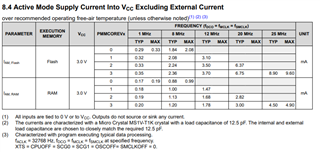
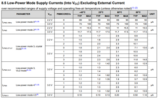
    I will be setting AVCC and DVCC voltage to 3.3V. Can you please let me know the supply current that can be considered for AVCC and DVCC power rail.

    Regards,

    Shifali N

  • Hi Shifali,

    That will depend greatly on what frequency you are running at, and what your code is doing. 

    Section 8.4 and 8.5 of the datasheet can give you a sense, but as you'll see it depends on your power mode and operating frequency.

    At 3.3V you can expect slightly higher current than at the 3V shown in the table, but we do not give an exact specification for 3.3V.

    Best Regards,
    Brandon Fisher

  • Hi Brandon,

    1. The VCC power mentioned in section 8.4 and 8.5 is AVCC or DVCC

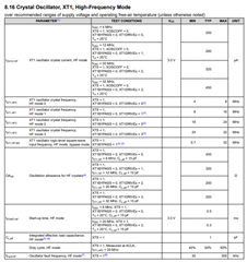
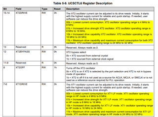
    2. What is HF_Mode=0, HF_Mode=1, HF_Mode=2 and HF_Mode=3. How to select the crystal frequency for XT2.

    3. Whether P3.3/UCB0CLK/UCA0STE pin can be used as general purpose IO.

    Thanks,

    Shifali N

  • Hi Shifali,

    1. The VCC power mentioned in section 8.4 and 8.5 is AVCC or DVCC

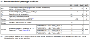
    When the datasheet uses VCC, its assuming AVCC = DVCC and they are from the same source, see the footnotes in our recommended operating conditions for details. 

    2. What is HF_Mode=0, HF_Mode=1, HF_Mode=2 and HF_Mode=3. How to select the crystal frequency for XT2.

    This is just referring to the setting for XT1DRIVE or XT2DRIVE. The higher these bits the higher the intended frequency range is.

    You should select a crystal that is within the frequency ranges specified in the datasheet. Crystal frequency is often a tradeoff between power consumption and operating requirements. You can run faster with a higher frequency crystal, but you will typically consume more power.

    Other things to note, ensure your ESR is less than the Oscillation allowance specified for each frequency range, and that you can tolerate the crystal accuracy specifications. 

    3. Whether P3.3/UCB0CLK/UCA0STE pin can be used as general purpose IO.

    Yes it can be. 

    Best Regards,
    Brandon Fisher

  • Hi Brandon,

    1. Which interface can be used to program MSP430.

    2. Do you have any schematics and layout guidelines document.

    Regards,

    Shifali N

  • Hi Shifali,

    Please post a new thread if you have additional questions that are not directly related to the thread topic. This improves findability for those who might have the same question in the future.

    1. Which interface can be used to program MSP430.

    Your options are 4-Wire JTAG, or you can use our 2-wire Spy-By-Wire interface.

    Please see our MSP430 Programming With JTAG document (https://www.ti.com/lit/slau320) for any specific protocol questions.

    There are also many programmers available commercially that make the process of programming an MSP430 very simple. Please see section 4.3 of our MSP430 Development Guide Book (https://www.ti.com/lit/slau840) for more information. The most convenient will be MSP-FET or MSP-GANG.

    2. Do you have any schematics and layout guidelines document.

    I don't believe there is one document containing all the information for hardware design with MSP430, as there are a lot of potential use cases, but here's a quick list for a few important items:

    • For guidelines surrounding the JTAG connection, see section 2 of our MSP430 Hardware Tool's Users Guide (https://www.ti.com/lit/slau278). 
    • For crystal selection and layout guidelines, see our MSP430 32-Khz Crystal Oscillators Guide (https://www.ti.com/lit/slaa322), and the device datasheet.
    • For ESD Recommendations (if relevant), please refer to our our System Level ESD Protection document (https://www.ti.com/lit/slaa530).
    • For connection of Unused pins, refer to the Family Users Guide (https://www.ti.com/lit/slau208 - Section 1.6 for this device)
    • For Power supply ratings, external bypass and bulk capacitor values, and most other things, refer to the device datasheet. 

    The MSP430 Development Guide book linked in the prior answer also includes a list of TI Reference designs, you can look that those for ideas if one seems similar to your application. 

    Best Regards,
    Brandon Fisher

**Attention** This is a public forum