Other Parts Discussed in Thread: MSP430F6638
Hi.
I am trying to implement I2C on MSP430F6435IPZ.
Since this is my first time using I2C, I got msp430f66xx_usci_i2c_standard_master.c from resource explorer for reference.
Within the GPIO initialization function
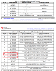
P2MAP0 = PM_UCB0SDA;
P2MAP1 = PM_UCB0SCL;
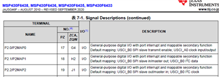
but the MSP430F6435 datasheet states that P2MAP1 is I2C data and P2MAP2 is clock.
(The MSP430F6638 had the same mapping.)
Why is it set like the reference?
The reference functions are as follows.
void initGPIO()
{
//LEDs
LED_OUT &= ~LED_PIN; // P1 setup for LED & reset output
LED_DIR |= LED_PIN;
// Disable Interrupts before altering Port Mapping registers
__disable_interrupt();
// Enable Write-access to modify port mapping registers
PMAPPWD = 0x02D52;
//I2C Pins
P2SEL |= BIT0 | BIT1;
P2MAP0 = PM_UCB0SDA;
P2MAP1 = PM_UCB0SCL;
// Disable Write-Access to modify port mapping registers
PMAPPWD = 0;
}