This thread has been locked.

If you have a related question, please click the "Ask a related question" button in the top right corner. The newly created question will be automatically linked to this question.

MSP430FR6047: TI algorithms fail to analyze waveforms but report Valid Results

Part Number: MSP430FR6047

We've been encountering an issue since the beginning of working with this chip where the TI algorithms fail to analyze waveforms. It's like TI refuses to analyze them. You can reset the module, reinitialize everything, and and take a number of different corrective actions, but the TI algorithms will NEVER work again until a reset is performed. Sometimes the TI algorithms start in this state. We don't think the waveforms matter either. We've tried storing waveforms in the code and using the same waveforms over and over again. Sometimes TI will process them and sometimes it fails on the exact same waveforms. Please find a brief debug console log below. It has been annotated to show the issue.

Reset reason: PMMSWBOR software BOR <------- !!!!!!!!!!!!!!!!!!!!!!!!!!!!!!!!!!!!
********************************
reconfigure_meter
Waiting for temperature

# Debug code:
    USS_absTOF_status_object status;
    USS_message_code code = USS_getAbsTOFStatus(&gUssSWConfig, &status);
    printf("%d  UPS(%d  %f  %s  %0.3f)  DNS(%d  %f  %s  %0.3f)    %+0.2f   %d   %d\r\n", code,
           status.UPS.indexMaxAmplitude, _IQ16toF(status.UPS.iq16Index), _stateText(status.UPS.state), data->algResults.totalTOF_UPS * 1e6,
           status.DNS.indexMaxAmplitude, _IQ16toF(status.DNS.iq16Index), _stateText(status.DNS.state), data->algResults.totalTOF_DNS * 1e6,
           data->algResults.deltaTOF * 1e12,
           data->algResults.messageCode, // <-- from TI's USS_Algorithms_Results
           signalAnalysis_getLastMessageCode()); // <-- USS_runAlgorithms() return value
# Annotated output:
#     (MaxIndex 1stPeakIndex Mode AbsTOF)      (MaxIndex 1stPeakIndex Mode AbsTOF)     dTOF     AlgResults.MessageCode   USS_runAlgorithms()
0  UPS(0  0.000000  search  59.227)         DNS(0  0.000000  search  59.227)           -25.41   0                        122

# ADC Delay adjusted for current temperature and body size:
#    gUssSWConfig.measurementConfig->startADCsamplingCount = newValue;
#    USS_updateSAPHConfiguration(&gUssSWConfig);
#    USS_initAlgorithms(&gUssSWConfig);
ADC Delay SAPH Count:  345 (69.00 us)  -->  348 (69.60 us, computed 69.65 us, error -51.7 ns)
0  UPS(0  0.000000  search  59.227)  DNS(0  0.000000  search  59.227)    -25.41   0   122

# Where we found the first peaks using our own algorithm
ADC First Peaks:  32 u  32 d

# TI always returns index 0 or 1 when in error.
# The AbsTOF numbers are very close to the ADC delay.
# TI always returns: 	USS_message_code_valid_results = 122
# even though the numbers are wrong.

ti failed to find a first peak
0  UPS(0  1.000000  search  59.228)  DNS(0  1.000000  search  59.228)    -22.68   0   122
ti failed to find a first peak
0  UPS(0  1.000000  search  59.228)  DNS(0  1.000000  search  59.228)    -22.68   0   122
ti failed to find a first peak
0  UPS(0  1.000000  search  59.228)  DNS(0  1.000000  search  59.228)    -22.68   0   122
ti failed to find a first peak
0  UPS(0  1.000000  search  59.228)  DNS(0  1.000000  search  59.228)    -22.68   0   122

# Meter detects the TI error and eventually resets. 
# It can take only 1 reset or hours of resets before the TI algorithm works as seen below

Reset reason: RSTIFG RST/NMI
********************************
reconfigure_meter
Waiting for temperature

0  UPS(0  0.000000  search  0.000)  DNS(0  0.000000  search  -0.000)    +0.00   11240   122
ADC Delay SAPH Count:  345 (69.00 us)  -->  348 (69.60 us, computed 69.65 us, error -49.7 ns)
0  UPS(0  0.000000  search  0.000)  DNS(0  0.000000  search  -0.000)    +0.00   11240   122
ADC First Peaks:  32 u  32 d
# Annotated:
# Water Temp                         v-- where math says the avg(U+D) AbsTOF should be      v-- where TI found it (our math isn't perfect)
 76.370 F | Center (+-5%)   60.47    63.65    66.83                                       | dTOF_Center  63.10 | AbsTof_Center  63.10
0  UPS(0  31.952118  track  63.096)  DNS(0  31.949249  track  63.096)    +14.27   0   122
0  UPS(0  31.946564  track  63.096)  DNS(0  31.952118  track  63.096)    +39.85   0   122
0  UPS(0  31.953186  track  63.096)  DNS(0  31.948669  track  63.096)    +13.19   0   122
0  UPS(0  31.950378  track  63.096)  DNS(0  31.952484  track  63.096)    +17.85   0   122

Since the TI algorithms are closed source, we can't debug this. We can only throw code at it and see if the TI results change without knowing why.

Thanks.

  • After testing a hunch, I think I've discovered part of the issue, but not having access to the TI source combined with the TI algorithm description in the Metrology Reference document not being entirely accurate, I can't say exactly what is happening.

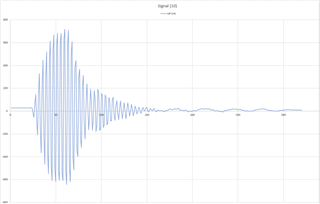
    Taking a step back, we noticed early in development that the ADC buffers often have a tiny peak right at the start of sampling, usually index <= 5. We've seen this "tooth" (as we call it) on both the eval board as well as our own. You can also see it in screenshots here in the forum and just barely (at index 0) in some of the TI documentation. Sometimes, the tooth, though small in amplitude, has a large slope. TI interpolates this small peak into a very tall peak which is sometimes close to the threshold value. Then TI uses this peak. To combat this, we started zero'ing out the first N samples of the buffer. We set the ADC delay to ensure that we never locate the signal too close to the start. Techniques attempted:

    * zeroing -- doesn't always work because the Nth + 1 data point may create a peak from the previous zero

    * flat -- all values up to N get the same amplitude as array[N] -- Mostly works, but we were trying to save processing time in TI code, so ...

    * ramp down -- array[0] = array[N] + N, then step down by 1 all the way to array[N]. The TI algorithms consider every point on a flat line to be a peak: if (N-1 <= N <= N+1) doInterpolation(). So, we were clever and ramped the signal down so that test can never be true. This is our current code. I suspect that TI may have a bug (that I also had in my code) where you start peak searching at index 0 instead of correctly at index 1. For example, if previousValue=0 and array[0] has a DC offset of 30 due to the hardware, then there's a peak at index 0 from amplitude 0 -> 30. The correct path is to set previousValue=array[0] and start the search at index 1. I'm not sure if TI is doing this, but it might explain the fixation with index 0 or 1.

    * flat (too high) -- I accidentally did this one. I set all points equal to the initial ramp down point. Visualize it as a horizontal line above array[N]. TI "track"s the first peak at N. Then, on the next measurement, track N-1. And then N-2 and so on until it reaches index 0. I don't know why it does this, but it hints potentially at how the TI algorithm works.

    I removed all manipulating of initial data and the problem has mostly disappeared. However, we will still now occasionally have the issue of TI interpolating an ADC artifact and finding a first peak around index 0-5.

    • Can you explain what is happening with the TI algorithms?
    • How do we prevent TI from finding the artifact peak?
    • Also, on a related note, why do the TI algorithms get worse and worse the further back in the buffer that the signal appears? If the signal starts at index 30, then generally no issues. But once the signal starts at index 50 or higher, the TI algorithms fail (wrong dtof, dtof shift errors, no signal found) at a much higher rate. This is even after validating that it finds the correct first peaks.
  • I've switch to the flat method, and it seems to be working. I haven't done any real world testing yet, though.

  • Hi,

    Could you send me the UPS and DNS data in your testing and also the USS_userConfig.h file? So I can take a look into it on what is happening. 

    Also, on a related note, why do the TI algorithms get worse and worse the further back in the buffer that the signal appears? If the signal starts at index 30, then generally no issues. But once the signal starts at index 50 or higher, the TI algorithms fail (wrong dtof, dtof shift errors, no signal found) at a much higher rate. This is even after validating that it finds the correct first peaks.

    And could you provide which related note said it? We do not think the algorithms fails are related to where the signal starts in the buffer. 

    Best regards,

    Cash Hao

  • Sorry for the delay. I'm handling something else at work. I'll reply when time permits. Thank you.

  • slaa837a page3

    It may say more later in the document. I found that one quickly, though.

  • Hi,

    Get it. Take your time. 

    slaa837a page3. It is just to remind the customer the ADC start time should be early than the signal arrives. We do not want to miss the starting part of the receive signal. Because it is important for the algorithm for calculation.

    Best regards,

    Cash Hao

**Attention** This is a public forum