This thread has been locked.

If you have a related question, please click the "Ask a related question" button in the top right corner. The newly created question will be automatically linked to this question.

MSP430FR2476: Problem modifying linker file to store PERSIST variables

Part Number: MSP430FR2476


Hello

I want to use the FRAM to store some persist variables for my aplication. Those are calibration variables, so it's mandatory that they are write/read.

I followed the example "msp430fr267x_framwrite_persistent.c" from CCS/resource explorer/MSPware and it works perfectly fine, but i don't know in which position those variables are stored on FRAM

#include <msp430.h>

// Statically-initialized variable
#ifdef __TI_COMPILER_VERSION__
#pragma PERSISTENT(Port_event)
unsigned long Port_event = 0;
#elif __IAR_SYSTEMS_ICC__
__persistent unsigned long Port_event = 0;
#else
// Port the following variable to an equivalent persistent functionality for the specific compiler being used
unsigned long Port_event = 0;
#endif

void initGpio(void);

int main(void)
{
    WDTCTL = WDTPW | WDTHOLD;               // Stop WDT

    // Configure GPIO
    initGpio();

    // Determine whether we are coming out of an LPMx.5 or a regular RESET.
    if (SYSRSTIV == SYSRSTIV_LPM5WU)        // MSP430 just woke up from LPMx.5
    {

        // Add the variable Port_event in FRAM to record the button event
        // Write protection starts from the beginning of Program FRAM + 1024 bytes
        // Code start address + 1024 bytes, Linker command file should be modified
        SYSCFG0 = FRWPPW | FRWPOA0 | DFWP | PFWP;// Configure 1024 bytes for FRAM write
        Port_event++;                       // Record the port event in FRAM
        SYSCFG0 = FRWPPW | DFWP | PFWP;     // Program FRAM write protected (not writable)

        do
        {

            P1OUT |= BIT0;                  // P1.0 = toggle
            __delay_cycles(100000);
            P1OUT &= ~BIT0;                 // P1.0 = toggle
            __delay_cycles(100000);

        }while (Port_event >= 5);           // Recorded 5 port interrupts?

    }

    // Device powered up from a cold start.
    // It configures the device and puts the device into LPM4.5

    P1DIR &= ~(BIT2);                       // Configure P1.2 as input direction pin
    P1OUT |= BIT2;                          // Configure P1.2 as pulled-up
    P1REN |= BIT2;                          // P1.2 pull-up register enable
    P1IES |= BIT2;                          // P1.2 Hi/Low edge
    P1IFG = 0;                              // Clear all P1 interrupt flags
    P1IE |= BIT2;                           // P1.2 interrupt enabled

    // Explicitly clear RTC control registers to disable it
    // just incase if the RTC was previously enabled
    RTCCTL = 0;

    PMMCTL0_H = PMMPW_H;                    // Open PMM Registers for write
    PMMCTL0_L |= PMMREGOFF;                 // and set PMMREGOFF
    PMMCTL0_H = 0;                          // Lock PMM Registers

    // Enter LPM4 Note that this operation does not return. The LPM4.5
    // will exit through a RESET event, resulting in a re-start
    // of the code.
    __bis_SR_register(LPM4_bits | GIE);
}

-- pragma PERSISTENT

#pragma PERSISTENT(Port_event)
unsigned long Port_event = 0;

-- write variable

// Add the variable Port_event in FRAM to record the button event
// Write protection starts from the beginning of Program FRAM + 1024 bytes
// Code start address + 1024 bytes, Linker command file should be modified
SYSCFG0 = FRWPPW | FRWPOA0 | DFWP | PFWP;// Configure 1024 bytes for FRAM write
Port_event++; // Record the port event in FRAM
SYSCFG0 = FRWPPW | DFWP | PFWP; // Program FRAM write protected (not writable)

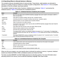
On the example's description, it mentions that "Linker command file should be modified to change memory partitioning and specify the location of PERSISTENT variables"

Could you give some and example on how to "place" the PERSISTENT variables in different memory locations?

Looking at the Application report SLAA628b, the example 3 (for CCS) shows how to allocate a new memory block + define a segment that store in this memory block.

1. Allocate a new memory block(MY_SECTION).

2. Define a segment(.Image) that store in this memory block(MY_SECTION).

3. Use #pragma DATA_SECTION in program to define variables in this segment.   

RAM                     : origin = 0x2000, length = 0x400    
RAM2                    : origin = 0xF100, length = 0x100    
MY_SECTION              : origin = 0xF200, length = 0x100    
FRAM                    : origin = 0xF300, length = 0xC80    

.Image      : {} > MY_SECTION   

#pragma DATA_SECTION(a,".Image")    unsigned char a;

The issue is that I'm not able to write variables on this new memory block using the method "--write variable" from the first example.

Should i declare this new memory block inside the FRAM section? if that’s the case, could you point me out how to do so? 

Also, I don't know if it's a good practice to create a new memory block instead of using the already declared PERSISTENT 

Best regards

  • For calibration I think that the information memory is a better choice. My preference is to create a structure holding the calibration data and then use memcpy() (or equivalent) to read it from information memory. No fiddling with linker scripts required.

  • Hi Albert,

    Some information about the persistent keyword can be found in the compiler's user's guide

    By default the persistent gets placed in the data section

    In the example you linked, if you open the linker file (.cmd) you can see how the memory organization is structured. 

    Regards,

    Luke

  • Thanks for both you you for your quick answer.


    The issue here is that I have a custom BOOTLOADER (using MSP430FRBoot as a base) on a separete project. This BOOTLOADER is 3K and resides in the main memory.


    The MAIN APP works well without bootloader, but when being loaded from BOOTLOADER It doesn’t work right. Also, if the main application does not use PERSISTENT variables, the application works fine being loaded from BOOTLOADER.


    Doing some testing I found out that the main issue is that there is a section from the application that gets stepped by the BOOTLOADER. That’s why I was trying to understand how to create data sections or to see if I could control where the PERSISTENT variables were placed


    The procedure I followed is:

    1. using “MSPFRBOOT_LinkerGen” to generate the linkers for BOOT and MAIN APP
      1. At this point, I was using the standard non-modified linker file from my MCU
    2. Compile BOOT using BOOT linker and generate an output file (BOOT.txt)
    3. Compile MAIN APP using MAIN APP linker and generate an output file (MAIN_APP.txt)


    To solve this issue, should I modify the linker file from the MAIN APP? My guess is that since PERSISTENT data is placed on .data, but that section is not reserved, the LinkerGen can place part of the BOOT application there, and later on, the MAIN_APP cannot write on those addresses since BOOT application is using them.


    Generating new memory block inside the FRAM section could solve this issue? How can i "block" a .data section so it doesn't get steeped by the bootloader?


    Best regards

  • Hi Albert,

    I think the MSP430 FRAM Devices Bootloader User's Guide has the information you need. For the boot configuration, I believe your boot linker file and your App linker file have different memory sections. What I recommend is to have your bootloader section off the area in FRAM for your calibration variables so it doesn't think the space is free.

    You can also change where the persistent variables are placed by partitioning your FRAM. So if you needed you could break up the FRAM block into a smaller section for your variables. In the linker file you can see in the "Memory" part they set FRAM to origin of 0x8000 and length of 0x7F80. What you can do is shorten the length of the linker files "FRAM" and create a new part to contain your calibration variables, just make sure the lengths match up so there is no overlap and you stay within the required sections of memory.

    Below is the memory organization so you know the range you are allowed to use.

    Regards,

    Luke

**Attention** This is a public forum