This thread has been locked.

If you have a related question, please click the "Ask a related question" button in the top right corner. The newly created question will be automatically linked to this question.

MSP430FR6047: Flow rate calculations

Part Number: MSP430FR6047
Other Parts Discussed in Thread: EVM430-FR6047

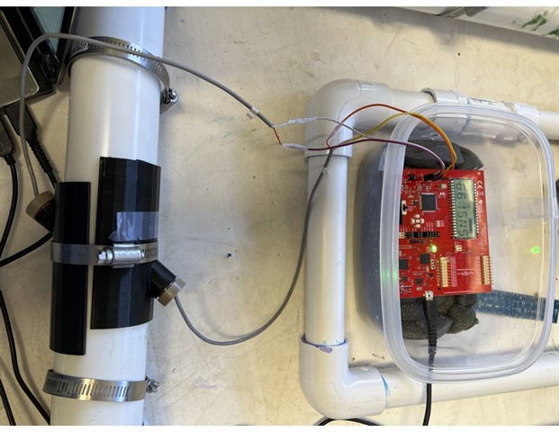
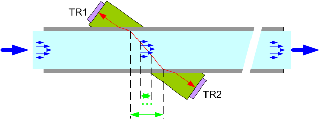
I am using the EVM430-FR6047 board with the clamp-on transducers Jiakang 1MHZ.  and 2-inch PVC pipe.

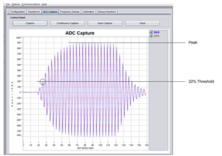
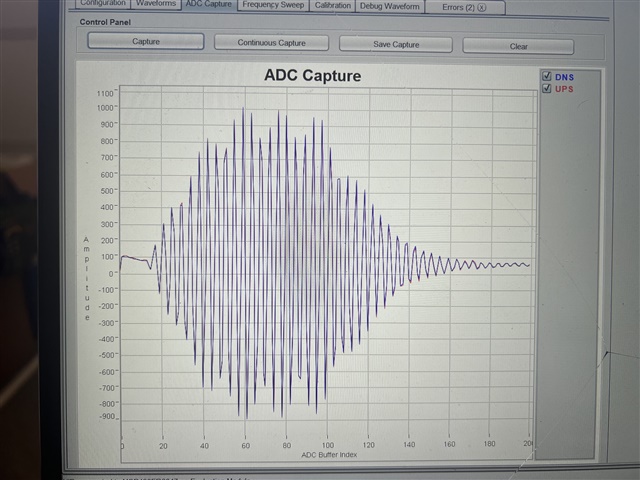
I am able to get the ADC to capture close to the desired capture as per the following document https://www.ti.com/lit/an/slaa949/slaa949.pdf

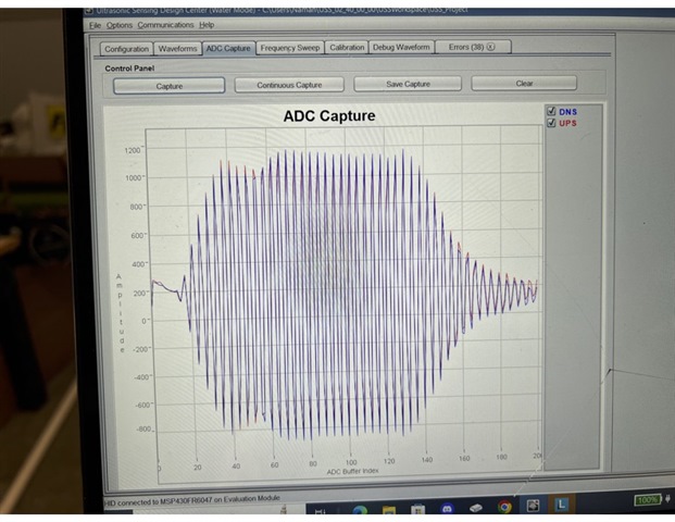
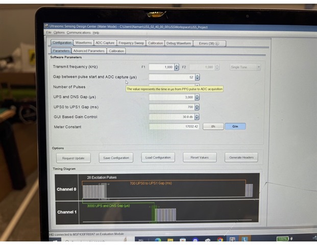
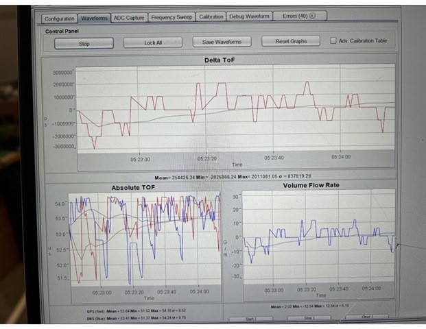
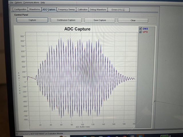
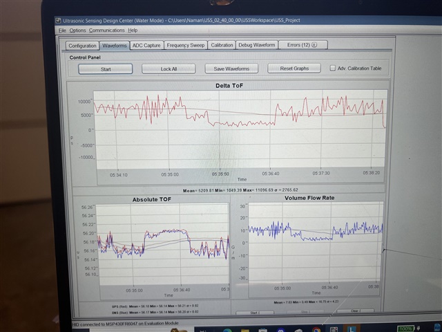
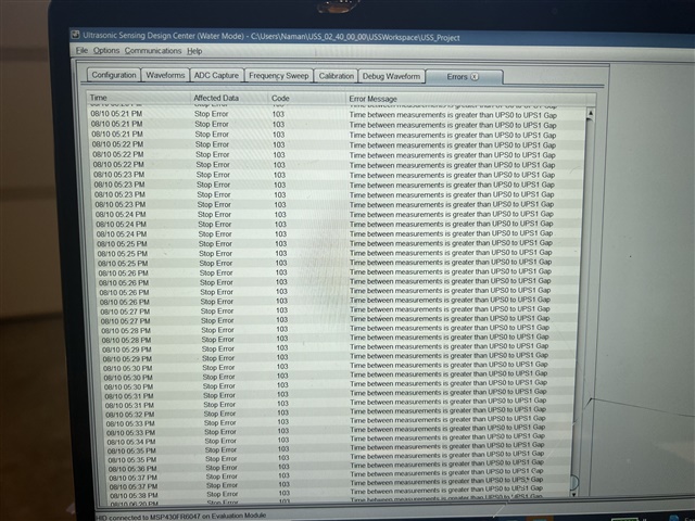
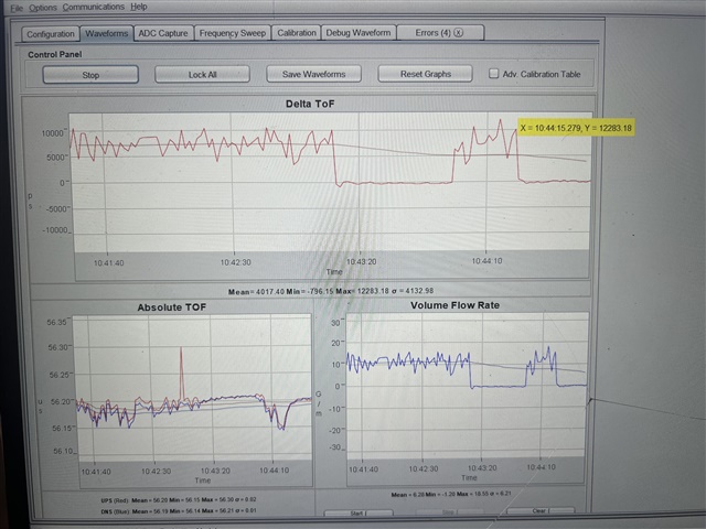
However, I am not getting the correct flow rate as it bounces up and down a lot you can see in the attached pictures.

Using a 3/4 inch pipe gives me correct flow readings. 

 Appreciate it if you can suggest any changes I should do to get the correct flow rate.

Thanks

Jaskarn

  • Hi Jaskarn,

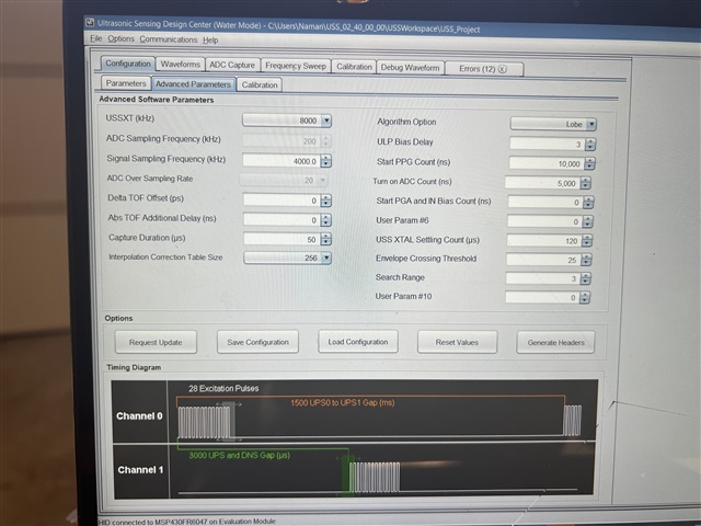
    The envelope of the waveform doesn't to rise and fall like most of our test images, your excitation frequency may not be optimal. Take a look at section 4.5 of this document and perform a frequency sweep as shown there (https://www.ti.com/lit/slau810).

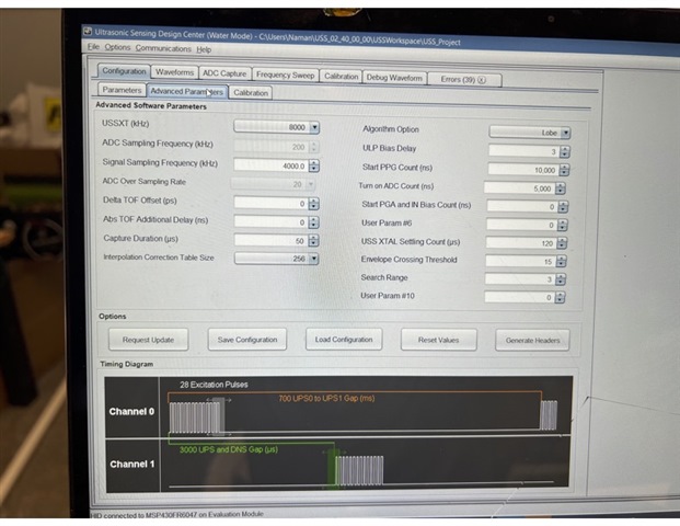
    Can you increase your envelope crossing threshold as well? It looks like it may be too low.

    You can also take a look at our MSP430 Academy on Ultrasonic Water Metering: https://dev.ti.com/tirex/explore/node?node=A__AJlj95sxbE600AgGSpHgoA__com.ti.MSP430_ACADEMY__bo90bso__LATEST

    Best Regards,
    Brandon Fisher

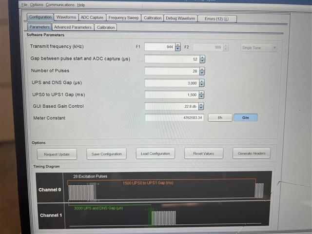
  • Thanks Brandon. Good suggestions. I followed them and see the expected results. Mostly it was the excitation frequency  revision needed and few other pararameters.  

    Here is my revised configuration and attached pictures. 

    I can see the flow gpm pretty much  correct  now when I reduce it or increase it on the 2 inch pipe. (maximum flow I have is 12GPM from my pump)

    Any further suggestions or advise ?

    Thanks so much again for your help. Love the support from TI 

  • Hi Jaskarn,

    I'm happy the results are improved. Your threshold also looks good to me now. It looks to me like there's still quite a bit of reflection though. There's quite a few extra peaks and troughs in the envelope. One of my colleagues recommends reducing the number of pulses. Start with 20, but you could possibly go even lower. 

    This may just be the angle of the image you shared, but it does look like the transducers could be a bit better aligned. If true that could also improve results.

    Are these ADC captures with flow? Do you have a zero flow ADC capture you can share? As an FYI the pipe should still be filled with water when taking a zero flow capture. 

    Best Regards,
    Brandon Fisher

  • Thanks for the quick response. I revised the number of pulses to 20 but I am not sure if it made much difference. See the attached ADC chart and DTOF calculations. I tested with max flow and zero flow. 

    I tried changing the positioning of the Transducers to align more but then I started loosing the right ADC capture. 

    Yes, all these tests were running with a close flow water loop testbed with max of 12 GPM. 

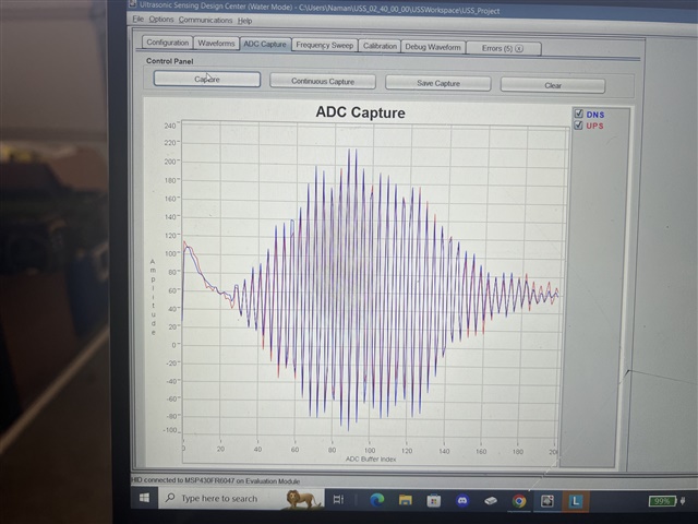
    The ADC chart with zero flow is also attached. Its the one with 240max amplitude. 

    Zero flow ADC capture. Here  I tried to stop the valve to keep the water flowing  in the pipe. 

    Let me know your thoughts/comments. 

  • Hi Jaskarn,

    The waveform looks close to normal to me. I'm not sure what is causing the initial pulse upward at the beginning, I can't say I've seen that before. 

    The STD on your delta time of flight is very high. Are you using a couplant of some kind?

    Best Regards,
    Brandon Fisher

**Attention** This is a public forum