This thread has been locked.

If you have a related question, please click the "Ask a related question" button in the top right corner. The newly created question will be automatically linked to this question.

MSP430I2040: single-ended meausurement

Part Number: MSP430I2040

Hello Team, 

my customer tries to use the differential input of the ADC to archive a signle ended measurement of an analog input signal. I think for this he will need additional component to feed the single ended input to the differential.

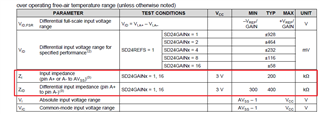
He has an offsetvolate issue when simply connects the A- pin to ground. can you also explain why this offset occurs? I guess it has do to with the circuit for the internal PGA:

I am currently working with the microcontroller MSP430I2040. The goal is to read out the analog signal with the internal ADC of the microcontroller. I noticed that the ADC pins have a voltage depending on the gain. At gain 1 10mV, at gain 2 20mV and so on. How does this happen and is this normal? The problem I have is that I connect the A- pin to GND. So there is a voltage of 40mV at pin A+ when I set it to gain 4 and when I set it to 30mV the ADC calculates a value of 70mV. What is the reason for this and how can I compensate the 40mV, so that only the 30mV are at the pin.

-------------------------------------------------------------------------------------------------------------------------------------------------------------------------------------------------------------------------------

yes exactly I try to realize a single-ended measurement.
The analog signal is a DC voltage of 0.4-2V. This drops over a voltage divider. The voltage divider breaks the voltage to approx.36mV-182mV.
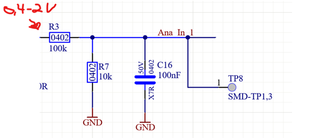
The Ana_In_1 network goes directly to the A+ pin of the ADC. A- is against GND.
If I have no voltage at all, i.e. 0V, then I measure a voltage of 40mV at TP8.
If I have for example 0,4V, then the voltage divider breaks the voltage to 36mV. But if I measure the voltage at TP8, then I measure a voltage of 76mV (36mV + 40mV). I suspect that there is a current of about 4.5uA coming out of the ADC pin and this is causing the 40mV. But how can this be or how can I fix this?

Thanks 

Jan

  • Hi Jan,

    I will invite our expert to help you.

    Thanks,

    Yuhao

  • Can you connect A+ and A- together to see whether the tested value is in spec: 

  • Hello Eason, 

    Here the answer of the customer:

    I got 0V between A+ and A- on my Eval-Board but if I connect A- to GND I got 10mV at gain 1. I do not know what to do with the A- pin.

    Regards 

    Jan

  • Hi Jan,

    Can you tell me what is your application? I want to understand from the whole system.

    If so, I think the input signal GND will have some gap between the MCU GND. Can you use a multimeter to test it?

    Eason

  • Hi Eason,

    The circuit is a 2-wire sensor whose signal is adjusted to 0.4V-2V with the help of a transistor and a resistor. This 0.4-2V drops across the voltage divider, resulting in a voltage of 36mV-182mV at the voltage divider. Based on this, I set the gain to 4. As mentioned before, the Ana_In_1 circuit is directly connected to the A+ pin. A- I set to GND. When the sensor is off, there is no voltage. However, at TP8 I measure the 40mV. At Gain 1 I measure 10mV.

    If I now switch on the sensor and a voltage of 36mV is set, I get a total voltage of 76mV at the TP8. It is important to mention that the ADC pins, which I did not initialize, have a voltage to GND of 0V. However, when I start the conversion, I get a voltage difference to GND at the ADC pin (A+ and A-) depending on the gain I set (Gain1 = 10mV... Gain 4 = 40mV). However, when I then measure the voltage between A+ and A- there is no voltage difference between the pins. I measured a current of about 4.5uA at TP8 at 40mV.

    I assume that a current flows from both pins. However, if A- is connected to GND, there is a differential voltage between A+ and A-. Is it possible that a single-ended ADC cannot be realized with a 2-wire? Or what do I have to do with the A- pin? Can it be that only 3-wire sensors should be used, because they have a GND connection ?
    To the second question I would like to say that there is no voltage difference between input GND and MCU GND.

    Jan

  • If I understand you correctly,

    1. If you use a mutlimeter, you also can test the offset when the sensor is off at TP8 right? But measured from MCU, the offset is 10mV. Right?

    2. Do you mean you use a mutimeter test the voltage with this "However, when I start the conversion, I get a voltage difference to GND at the ADC pin (A+ and A-) depending on the gain I set (Gain1 = 10mV... Gain 4 = 40mV)."

    3. I think the ADC don't have single-end limitation. I would suggest you to use a LDO to directly connect to the A+ and A-. The problem I think of your applicaiton may have is the PGA input impendence.

  • 1. yes that is correct. However, the offset depends on the gain.
    2. yes exactly. I measure with a multimeter between GND and A+/A- an offset depending on the gain.
    3. I think so too. However, I do not know yet exactly how to solve the problem. If I found a solution I would write this of course also in the forum.

  • Thank you very much, I am not sure if it is OK for your to add a buffer before the I204x. 

**Attention** This is a public forum