Hi,
I'm trying to bring up the I2C peripheral on an MSP430FG6426 in slave mode (BeagleBoneBlack - BBB is master).
What I know:
1. I can used "i2cdetect -y 1" on BBB to detect MSP and other devices on the bus.
2. I can transfer data on the same I2C bus from another device to the BBB.
3. When I execute the read I get the chars below. "`abcdpqrst" are the chars I'm expecting and I get exactly 64 bytes again as expected.
Address: 0x55
rx_len: 64
Data:
`abcdpqrst`abcdpqrst`abcdpqrst`abcdpqrst`abcdpqrst`abcdpqrst`abc
omap_i2c 4802a000.i2c: controller timed out
Error: Connection timed out (os error 110)
omap_i2c 4802a000.i2c: timeout waiting for bus ready
Error: Connection timed out (os error 110)
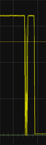
4. From the scope I can clearly see that both SCL & SDA are pulled low. The moment I reset the MSP SCL & SDA returns to 3.29V, indicating that in fact the MSP is holding it low.
5. I'm using a slightly modified driverlib example code (usci_b_i2c_ex4_slaveTxMultiple.c) with TI compiler v21.6 LTS. Biggest modifications: 1. it is not alone (while loop is not here), 2. I'm using USCI_B1. For clarity here is the whole code
#define SLAVE_ADDRESS 0x55
#define TXLENGTH 0x09
uint8_t transmitData[] = { 0x60, 0x61, 0x62, 0x63, 0x64,
0x70, 0x71, 0x72, 0x73, 0x74};
uint8_t *transmitDataPointer;
uint8_t transmitLength = TXLENGTH;
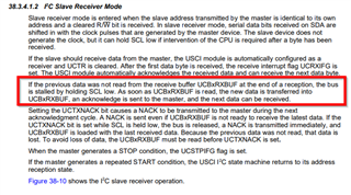
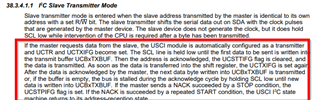
//38.3.4.1.1 I2C Slave Transmitter Mode
void i2c_init(void)
{
//Assign I2C pins to USCI_B1
GPIO_setAsPeripheralModuleFunctionInputPin(GPIO_PORT_P8, GPIO_PIN5 + GPIO_PIN6);
//Initialize I2C as a slave device
USCI_B_I2C_initSlave(USCI_B1_BASE, SLAVE_ADDRESS);
//Set in transmit mode
USCI_B_I2C_setMode(USCI_B1_BASE, USCI_B_I2C_TRANSMIT_MODE);
//Enable I2C Module to start operations
USCI_B_I2C_enable(USCI_B1_BASE);
//Enable master transmit interrupt
USCI_B_I2C_clearInterrupt(USCI_B1_BASE, USCI_B_I2C_TRANSMIT_INTERRUPT + USCI_B_I2C_STOP_INTERRUPT);
USCI_B_I2C_enableInterrupt(USCI_B1_BASE, USCI_B_I2C_TRANSMIT_INTERRUPT + USCI_B_I2C_STOP_INTERRUPT);
transmitDataPointer = transmitData;
transmitLength = TXLENGTH;
//Enter low power mode 0 with interrupts enabled.
// __bis_SR_register(LPM0_bits + GIE);
// __no_operation();
}
//******************************************************************************
//
//This is the USCI_B1 interrupt vector service routine.
//
//******************************************************************************
#if defined(__TI_COMPILER_VERSION__) || defined(__IAR_SYSTEMS_ICC__)
#pragma vector=USCI_B1_VECTOR
__interrupt
#elif defined(__GNUC__)
__attribute__((interrupt(USCI_B1_VECTOR)))
#endif
void USCI_B1_ISR(void)
{
uint16_t iv = UCB1IV;
USCI_A_UART_transmitData(USCI_A0_BASE, iv + 0x61);
switch (__even_in_range(iv, 12))
{
case USCI_I2C_UCSTPIFG:
//Exit LPM0 if data was transmitted
__bic_SR_register_on_exit(LPM0_bits);
break;
case USCI_I2C_UCTXIFG:
//Transmit data
//if (transmitLength > 0x00)
{
USCI_B_I2C_slavePutData(USCI_B1_BASE, *transmitDataPointer++);
//transmitLength--;
if (transmitDataPointer >= (transmitData+10))
{
transmitDataPointer = transmitData;
}
}
break;
default:
break;
}
}
Questions:
1. Why are both the SCL & SDA pulled low?
2. Separately how can I indicate to master that I have nothing to send? Do I just send 0x0 or 0x20 and on the other end that should mean I should not be asking anymore?
3. Is there a way to force MSP to release I2C bus?