This thread has been locked.

If you have a related question, please click the "Ask a related question" button in the top right corner. The newly created question will be automatically linked to this question.

MSP430AFE253: Differential ADC sampling data is abnormal in an interfering environment

Part Number: MSP430AFE253


Hi team,

There’s an issue from the customer need your help:

Hello, I use MSP430AFE253IPWR to design a module that collects small voltage signals, the acquisition frequency is fixed, in the field environment test or in the factory simulation of an interference environment, the ADC collected the value is abnormal, this interference in the company test is a fixed frequency.

Normal (no interference) waveform:

There are interference waveforms:

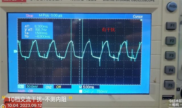
I want to realize that normal small voltage signals can be collected when there are interference waveforms, and I want to ask TI MCU itself whether there is a filtering algorithm in this regard, or whether there are any filtering suggestions.

Thank & Regards,

Ben

  • Hi Ben,

    To help me better answer your questions, I need some additional information from you.

    collects small voltage signals,

    What range in voltage are these signals?  0.001v ? 0.01v? 0.1v?, etc.

    What is the source of electrical noise? Can you provide what type, how strong, how close to the ADC? and is there a particular frequency?

    What is the signal source the ADC is measuring? Output from sensors? voltage across resistors?, etc.

  • Hi Dennis,

    At present, in the case of interference source, the measured AD value is the superposition of the normal signal and the interference signal. How to filter out this interference signal and only retain the normal signal? The voltage range does not need to be considered. It can always be 0V. In the case of ADC is 0, it will also be disturbed and collect outliers. We need to Except for the outlier value, it is displayed as 0V, and the value of the interference is filtered out. The source of interference is frequency 50HZ or 100HZ.

    Best Regards,

    Ben

  • I assume that you are employing proper grounding and shielding practices to protect the signal.

    It looks like you are having trouble with line frequency noise. If you can't keep it out then the best bet is a filter with a notch at 50Hz. A Sigma-Delta converter with an output sample rate of 50Hz would do that. Or a moving average filter with a period of 20ms.

  • Hi Ben,

    Yes, David is absolutely correct. Is the signal the ADC is measuring on the same PCB or does it come from another PCB with cabling connecting the PCBs, or maybe an external sensor that connects to your PCB?  I ask these questions because I'm trying to understand how/where the noise is getting into your signal channel but first need to understand the path between the ADC and the signal voltage it is measuring.

    To David's point, are you using any filtering before the ADC input?

     Is it possible to share a photo of your setup with your oscilloscope connected to the circuit?

**Attention** This is a public forum