This thread has been locked.

If you have a related question, please click the "Ask a related question" button in the top right corner. The newly created question will be automatically linked to this question.

MSP430F5521: Programming issue

Part Number: MSP430F5521
Other Parts Discussed in Thread: ISO35T

Hello,

We have a design that is in serial production for many years.

In the last batches over a period of few months, we have a problem after programing the device via JTAG. We use the UART to communicate via RS485 with a PC terminal.

After power up, instead of receiving the menu, the CPU transmits gibberish characters.

At the beginning we are replacing the CPU with a new one and the problem disappeared. Recently even if we replace the CPU on the board doesn't help and we found out that with an old version it seems that everything works fine.

We have reviewed SW code and it looks OK.

WE also tried to problem the device before assembly on the PCB in a external JIG with the socket and it doesn't help

From all the tests we have done it seems there is a problem with the device. At the moment all the devices we have show this problem

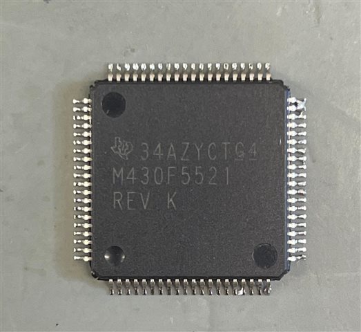
This is the device with problem

  • Have you looked at the "gibberish" to see if there is a pattern? Sounds like a timing issue to me and your baud rate is off. Are you using a crystal?

  • Hi Keith

    Thanks for your comment! I think Adrian Lofer can test clock at the first step

  • We tried with internal clock and external crystal.

    Also swapping CPUs between two boards, the problem moves with the CPU.

  • Thanks. All clocks are OK

  • Hi Adrain

    May I know how many units of MCU have been tested?

    Thanks

  • tens of MCUs have been replaced.

    The thing is when I replace MCUs the problem always moves with the problematic part.

    The interface device is TI ISO35T connected directly to the MCU UART.

    I've the 

    MSP-TS430PN80USB - 80-pin Target Development Board for MSP430F5x MCUs

    and not ordered the ISO35T development board. 

    This way I can test everything away from my HW. hope I can find the root cause either in MCU or SW.

    Attached is a code we use to debug the problem showing the way we configure the clocks and the UART in the MCU.

    Maybe someone can find a mistake of and register what was wrongly or not initialized.

    /**************************************************
     * main_5521.c
     * 
     *  
     *
     * 
     *
     * zur shimon
     *
     **************************************************/
    
    #include <msp430.h>
    //
    #define EXTERN 
    #include "var_def.h"
    
    
    //
     #include "com_all.h"
    
    char  rd_sw(void);
    void musb(void);
    void write_SegX(char value);
    void set_com_for_TX(void);
    /**************************************************
     *int main(void)
     * 
     * 
     *
     * 
     *
     **************************************************/
    
     int main(void)
    {
    
     
      WDTCTL = WDTPW + WDTHOLD;                 // Stop WDT
      P3SEL = BIT3+BIT4;                        // P3.4,5 = USCI_A0 TXD/RXD
      
      //
      P5SEL |= BIT4 + BIT5; 
      //
      
     
      UCSCTL2 |= 144;  
     
    ///
     UCSCTL1 =0x30;


      __delay_cycles(100000/10);// delay for ~3ms
      ////
     
      P3SEL |= BIT3+BIT4;                       // P3.3,4 = USCI_A0 TXD/RXD
      UCA0CTL1 |= UCSWRST;                      // **Put state machine in reset**
      UCA0CTL1 |= UCSSEL_2;                     // SMCLK
    
     UCA0BR0 = 238;                              // 
      UCA0BR1 = 1;    
     // UCA0MCTL |= ( UCBRF_0);   
        UCA0MCTL |= UCBRS_3; 


      UCA0CTL1 &= ~UCSWRST;                     // **Initialize USCI state machine**
      UCA0IE |= UCRXIE;                         // Enable USCI_A0 RX interrupt
    
         UCA0CTL1 |= UCSSEL_2 + UCRXEIE;           // SMCLK; receive erroneous bytes


        P2DIR |=(BIT5|BIT6);
        set_com_for_RX();
       
    __bis_SR_register(LPM0_bits + GIE);       // Enter LPM0, interrupts enabled
      __no_operation();                         // For debugger
    }
    
    // Echo back RXed character, confirm TX buffer is ready first
    
    #pragma vector=USCI_A0_VECTOR
    __interrupt void USCI_A0_ISR(void)
    
    {
    char in_data;
      switch(__even_in_range(UCA0IV,4))
      {
      case 0:break;                             // Vector 0 - no interrupt
      case 2:                                   // Vector 2 - RXIFG
        
        while (!(UCA0IFG&UCTXIFG));             // USCI_A0 TX buffer ready?
     // set_com_for_TX();
        //   set_com_for_RX();
       in_data = UCA0RXBUF; 
    
       set_com_for_TX();
       
       
        UCA0TXBUF =  0x55;                  // TX -> RXed character
        while(1)
        {
         __delay_cycles(100000);
         UCA0TXBUF =  0x55;   
        } 
         
    set_com_for_RX();
        break;
      case 4:break;                             // Vector 4 - TXIFG
      default: break;
      }
    }


    void set_com_for_TX(void)
    {
     
     __delay_cycles(10000);
      P2OUT |=BIT6 ; 
        P2OUT |=BIT5 ; 
      __delay_cycles(10000);
      
    }// end  void timer_utl(void)
    
    
    void set_com_for_RX(void)
    {
      // P5DIR |= BIT6;                            // led set as output
         __delay_cycles(10000);
     P2OUT &=~BIT5 ;
     P2OUT &=~BIT6 ; 
       __delay_cycles(10000);
    }// end  void timer_utl(void)
    
    
    void print_text(char *txt)
    {
      set_com_for_TX();
       char i=0;
        while(*(txt+i) >0)
        {
          while (!(UCA0IFG&UCTXIFG));             // USCI_A0 TX buffer ready?
         UCA0TXBUF =  *(txt+i);
          __delay_cycles(10000);
          i++;
          
        }
     
     // wr_crlf();
    }


  • Again, have you looked at the "gibberish" to see if you can find a pattern?

  • Gibberish from a serial data stream says that data is being sent but that there is a disagreement on bit rate.

    Difficult to follow what you are doing here nor can I tell your intentions. Nobody comments their code anymore.

    UCSCTL2 |= 144 is problematic because that register is not zero after a reset.

  • unfortunately no pattern. Every time it is different

  • Thanks David,

    Can you provide me a sample code or a register and peripheral configuration for UART at 9600. external crystal 32.768Khz

  • Such as provided in the code examples in slac300?

  • we used slac300. But maybe we have missed something

  • Hi Lofer

    Please check the UART setting on MSP430F55xx_uscia0_uart_03.c of slac300

    UCSCTL4 |= SELA_0 + SELS_4 + SELM_4;     

    // ACLK = LFTX1
    // SMCLK = default DCO
    // MCLK = default DCO

      UCA0CTL1 |= UCSWRST;                      // **Put state machine in reset**
      UCA0CTL1 |= UCSSEL_1;                     // CLK = ACLK
      UCA0BR0 = 0x03;                           // 32kHz/9600=3.41 (see User's Guide)
      UCA0BR1 = 0x00;                           //
      UCA0MCTL = UCBRS_3+UCBRF_0;               // Modulation UCBRSx=3, UCBRFx=0
      UCA0CTL1 &= ~UCSWRST;                     // **Initialize USCI state machine**
      UCA0IE |= UCRXIE;                         // Enable USCI_A0 RX interrupt

    Thanks!

  • Yes, but is the baud rate the same? Is the bit timing consistent?

    If it is sending random data at the consistent timings and the correct baud rate, that points to an issue with the USCI, rather than the clock system.

**Attention** This is a public forum