This thread has been locked.

If you have a related question, please click the "Ask a related question" button in the top right corner. The newly created question will be automatically linked to this question.

ADC10SHTx - ADC10_B sample and hold time. MSP430FR5739

Other Parts Discussed in Thread: MSP430G2452, MSP430FR5739, MSP430F5438

Hello,

I don't really understand how many ADC10CLK cycles i should choose in the sampling period for the ADC10.

Most of the ADC10 examples choose ADC10SHT_2 = 16 cycles, so is this the case to use mostly or do you only set when using ADC10 in Pulse Sample Mode (section 16.2.5.2 in SLAU272)

I just want to sample a low DC voltage (< 5V).

Thanks

Michael Dalton

  • Michael Dalton said:
    I don't really understand how many ADC10CLK cycles i should choose in the sampling period for the ADC10.

    It depends on your application.

    See the chapter in teh users guide. The ADC10 has an internal capacitoor that is charged during the sample period and (slightly, the faster the conversion, the less it is discharged, the better the result) discharged during the conversion.

    This capacitor (See datasheet for your MSPs value Ci) together with the input switch impedance of 1kOhm and the output impedance of your signal source forms a low pass. Depending on the maximum frequency you want to sample and the worst case minimum precision you want to achieve, you need to give this capacitor some time to charge (it is a nonlinear charge function). R*C gives the time constant Tau. 1Tau gives you 70% charge level. But 70% is only 2 bit precision. For 10 bit resolution (1/2 LSB precision), you want the capacitor charged to 1-1/2048 of the input voltage. (99.95%). It is R*C*ln(2^11) or 7.6Tau. How long Tau is, depends on your signal source (output Impedance) and how many clock cycles it is, depends on your ADC10 clock speed. Only you can know.

  • Hey Jens,

    For the life of me i could not fine the value for Ci in the http://www.ti.com/lit/ds/symlink/msp430fr5739.pdf document, so i picked the value of 5pF from the http://www.ti.com/lit/ds/symlink/msp430g2452.pdf datasheet.

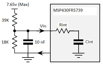
    So my circuit looks like the following

    so

    Rin = [(39K * 18K)/(39K + 18K)] + Rint

    Rin = 12.3K + Rint = 12.3K + 1K = 13.3K ohms

    So Tau ~=13.3K * 5pF =66ns

    7.6*Tau = 505ns

    Im using MODOSC for the ADC10CLK so thats around 5MHz sooooooo,

    505ns * 5MHZ = 2.5 cycles round up to 4 so a ADC10SHT_0 is good enough?

  • The FR datasheed is very incomplete (under development).
    However, 5pF is not much. Are you sure? I've seen 25pF as well (MSP430F5438).

    However, with your 10nF as buffer, the R is with 1k relatively low, so the TAU is very small.
    Also, if the input value is only slowly changing, the Cint is precharged after a few cycles, so the required gate time decreases.

  • Yeah ok,

    So apart from wasting processing time with unnecessary  cycles, is there any harm in having a larger ADC10SHT than necessary?


    Regards

    Michael Dalton

  • Sampling too long will also introduce sort of a low-pass filter to your signal. But that's rather a benefit, as it reduces noise.
    So if your sampling frequency allows it (Nyqvist theorem), a long S&H time doesn't hurt nor does it increase current consumption. It does, however, expose at least the static input impedance to the signal source during the SHT time. So when sampling very high impedance signals, SHT shouldn't be longer than necessary (but also not shorter).

**Attention** This is a public forum