This thread has been locked.

If you have a related question, please click the "Ask a related question" button in the top right corner. The newly created question will be automatically linked to this question.

Problem on completely disabling the USB port. (consumes extra ~400uA even after disabling the USB)

Other Parts Discussed in Thread: MSP430F5528

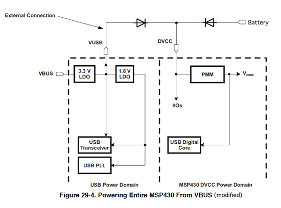
I am using MSP430F5528 for a battery operated device. I use the TI BSL (through USB port) to write the new firmware. Once the BSL firmware upgrade completes, then it executes my firmware. On startup, I do not turn on any devices and set every pins on the MSP to a valid state to save power. I unplug the USB cable after BSL.

My target is 350uA. But I am ending up with 750uA.

BUT when I unplug the battery and plug in back in I get 350uA. That means, the USB module is running even after the BSL is  completed. I tried disabling the USB by calling USB_init(), USB_disable(), USB_disconnect(). No luck. I also initialize each & every USB registers on the MSP to 0 to make sure everything is in a PUR state.

Can anybody tell me what I am doing wrong here which causes an extra 400uA power consumption?


Any response is appreciated,


  • Hi Ibrahim,

    A couple of thoughts:

    1. Did you remember to "unlock" the USB control registers before clearing them?  You must write the USBKEY to USBKEYPID.
    2. How do you know it's the USB module drawing the extra 400uA and not some other module?  There are a few modules/settings that only reset with a POR and not with a PUC.
    3. You may be able to learn a lot about this problem if your startup code induces a PMMSWPOR whenever the source of the last reset is not PMMSWPOR.  You might even decide to use it as a permanent workaround if you can't find the cause of the 400uA.  (PMMSWBOR would also be an option.)

    Jeff

  • Jeff,

    Thank you so much for the reply.

    1. Yes. the 'unlock' was done prior to clearing them.

    2. There are two reasons why I am doubting the USB.

       a. My firmware was running before calling the BSL (I am calling 0x1000 directly); at this point consumption was ~350uA, I upgraded to the same firmware through BSL and now the consumption is ~750uA.  So I checked the BSL source code to see what are the modules it uses and all I could not think of anything other than the USB module.

       b. When my firmware runs at 360uA; I use a push button to enable the USB port and consumption jumps to 750uA. So I assumed that USB takes ~400uA.

    But you are right, it could be some other module. I have already turning off TIMER1, TIMER2, UART, I2C, SPI, PWM, and set all DIO pins to appropriate state. So now I will check with clocking modules.

    3. After using the BSL to download the firmware, I am executing the forced_PUC.txt through BSL which has the following contents.

    @0120

    A5 02

    q

    I try both PMMSWPOR  & PMMSWBOR  tomorrow to see if that makes any difference.

    Regards

    Hamsa


  • Sound like your board supplies 3V3 rail to the Vusb pin from the on-board power source (battery?).
    If so, cut off Vusb pin from the on-board power. Connect just a 220nF capacitor to Vusb pin.


    The code of TI's USB package supposes that the USB power domain of the chip is separately supplied from USB connector over the VBUS pin. As the default after power-up, the on-chip USB 3V3 regulator is enabled (USBPWRCTL.VUSBEN). On the source code, the USB 3V3 regulator is kept enabled, as follows.

    MSP430_USB_Developers_Package_3_0_0_0\MSP430_USB_API_Stacks\examples\...\USB_API\USB_Common\usb.c

    BYTE USB_init(VOID)
    {
        ...
        USBPWRCTL   =     VUSBEN + SLDOAON; // enable primary and secondary LDO (3.3 and 1.8 V)


    On the USB BSL code, the USB 3V3 regulator is enabled, too.

    SLAA450.zip - \Custom_BSL_Zip_File\BSL_Source\Peripheral_Interfaces\USB\usb.c

    VOID USB_init(VOID)
    {
        ...
        USBPWRCTL  = VUSBEN + SLDOEN + SLDOAON + VBOFFIE + VBONIE; // enable interrupt VBUSoff, VBUSon, keep primary and secondary LDO (3.3 and 1.8 V) enabled


    In this way, the USB power domain doesn't draw any current from the battery.
    To enable BSL without on-chip battery, you may add diodes across Vusb/DVCC pins.


    Tsuneo

  • Tsuneo & Jeff,


    You both helped me identifying the problem.


    Tsuneo, There is actually a capacitor on the VBUS already on our board. But by sending the latest BSL code snippet, you helped me identifying the problem.


    Jeff, you are correct, it’s not the USB but the timer B. In the PI_init() function of the BSL, it is turning on the timer B (TBCTL) and not turning off. I missed that one.


    (SLAA450\Custom_BSL_Zip_File\BSL_Source\Peripheral_Interfaces\USB\BSL430_USB_PI.c)


    Now my code works great the battery consumption ~360uV as I wanted.


    Thanks a lot,

    Regards

    Hamsa


**Attention** This is a public forum