Part Number: MSP430FR6043
This is the diagram found in the uC data sheet which uses both channels to pulse/read a single pair of transducers in both directions.

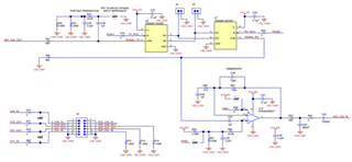
This is how TI designed it on the demo board, using only CH0 and switches U8 and U9 to select the direction:

To orient you to this schematic:
- AFE_CH0_OUT is the pulse generated by the uC.
- U9 is a voltage level shifter that allows us to pulse the transducers at a higher voltage (VCC-TX) than the uC is running on (VCC-RX)
- J5 and J6 connect to the transducers.
- U8 and U7 switch which transducer is upstream/downstream.
- U10 is an amplifier, the output of which (AFE_CH0_IN) is fed back to the uC for analysis.
Questions:
-Why doesn’t the demo board use both channels? I’m assuming it was to avoid building the level shift circuit and amplifier for both channels.
-Is there any advantage of using both channels instead of multiplexing CH0?
-On the demo board schematic SIGNAL_RX coming out of U7 and leading to the amp (U10) is also routed back to the level shifter (U9). Why would SIGNAL_RX need to go back to U9?