This thread has been locked.

If you have a related question, please click the "Ask a related question" button in the top right corner. The newly created question will be automatically linked to this question.

MSP430FR6043: MSP430FR6043 for ultrasonic

Part Number: MSP430FR6043
Other Parts Discussed in Thread: EVM430-FR6043

Hello Team,

There are 2 questions that need your help,thanks!

1. Could you pls share the MSP430FR6043 source code, we need to do secondary development on it, for mix gas ultrasonic flow meter;

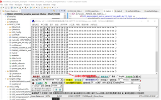
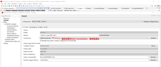
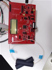
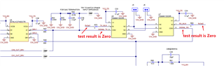
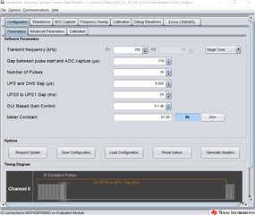
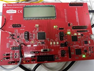
2. The development board EVM430-FR6043 was connected to the TI PC software USS, it was normal at the beginning, and our own ultrasonic sensor was connected to the development board, the frequency is 1MHz, after modifying the frequency parameters on the USS modification several times, the USS and the development board can not communicate normally, the details are as follows:

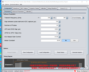
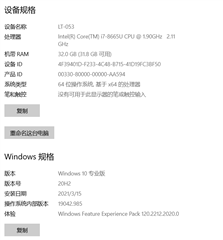
The computer development environment.

  • Hello,

    Please accept my friend request so we can exchange emails in private to discuss access to the USS source code.

    As for you issue with the bridge waiting: Have you tried resetting or re-flashing your device with the demo code? This error message means that the EVM is not communicating normally with the PC. What was the last thing that you changed before the communication stopped?

  • Hello Dylan,

    Mybee friend request were lost, you can accept my request.

  • Hello Dylan,

    we change the "transmit frequency", then "request update", the error occured. Just now , we "Reset values" but still not be resolved.

  • I am saying that you should try resetting and/or re-flashing the device with the demo code to see if this helps. Have you edited the demo code at all? Adjusting the transmit frequency and requesting an update should not normally cause the device to hang.

  • Hello Dylan,

    Do you have an UART profile about the EVM430-FR6043, my customer find the EVM is communicate with PC through USB-HUB. However, they need the communicate with I.MX6 without USB-HUB. so, could you share the UART transfer protocol?

    Thanks!

  • In the same directory as the USS gas demo, there should be a project titled FR6043_USSSWLib_template_example. This example includes the same USS functionality as the gas demo, but it removes the GUI interface and adds a UART debug interface. Please refer to that example.

  • Hello Dylan:

    we rebuild the FR6043_USSSWLib_template_example, and download to the EVM430-FR6043 board, EVM communicates with PC through MSP-FET430UIF, then open Serial Assistant on the PC, but we can't find data on the Serial Assistant,   how  to get the ATOF/DTOF/VFR data on the Serial Assistant. The settings of Serial Assistant are as following:

  • Hi Wang,

    I think I was unclear in my previous response; I will elaborate.

    I meant to say that the template example will show how to use the MSP430FR6043 to collect all of the ToF and VFR data, and transmit them out via UART. This example is still debugged in the same manner as previous projects. So you should not need to change the connection in project properties.

    I am not familiar with the serial assistant tool you are using, and I am unable to read a lot of the window that you've posted an image of. I assume that it is just a serial terminal interface. However, once you've implemented the template example you should be able to view this data on the device's UART pins using a standard UART interfacing device.

    If instead you are attempting to utilize the UART feature for the HID Bridge (which uses I2C by default), you'll need to configure the jumpers on your device as described in the EVM430-FR6043 hardware guide. Then you should check that your project defines COMM_SERIAL_INTERFACE as COMM_UART. This define is found in comm_config.h.

  • Hi Dylan Obrien:

    The FR6043_template  example can show the ToF and VFR data, but all the data are Zero, why?

    figure 1

    figure 2

  • Hi Wang,

    It is a little hard to tell in your image, but I think your jumper configuration is correct. To double check, could you review the default jumper configurations shown in section 2.1 of the EVM430-FR6043 Hardware Guide.

    Are you certain that you are getting a good measurement / good data from the transducers? You could confirm this by reverting to the Demo code and viewing it in the GUI.

    Have you altered the template example at all? When I utilize the template example, I am able to switch from the demo code to the template code without changing my hardware, just changing the project and re-programming my device. Then I probe the pins using an external logic analyzer. Have you tried probing the pins to look at the waveform? This could be helpful.

  • Dear Dylan OBrien:

    I revert the template example code to Demo code and view the signal in the GUI that Using the same transducers. I think the transducers are good.

    I have never altered the template exanple. I probe the signals, such as RxSel1、RxSel2、SIGNAL_TX、SIGNAL_RX, they are all Zero, no waveforms. I think maybe these casuse the UART data to Zero. Where to set up these signals in the template example program?

  • These should all be set up already in the template example. For me, when I flash the template example to the device, I do not have to alter the board or the example at all to get test data from the UART. Especially considering that you do see the correct waveform when using the demo, I do not suspect the problem is with the hardware. To verify, could you please post an image of your ADC capture from the demo here?

    Have you also probed those pins while running the template example to make sure that you can see the waveform on the scope then?

    Additionally, are you just using the backchannel UART to the PC in order to view the UART data? Have you considered viewing the output of the UART port directly with something like a logic analyzer? This is how I have viewed the UART data in the past, rather than using the backchannel UART. You may find more success by viewing it that way. By eliminating the backchannel UART and viewing it with a logic analyzer or an oscilloscope there is less room for error and we can narrow it down to the MSP430FR6043, without having to worry about the debugger.

    If you have not changed the device hardware, have verified your jumper configurations, and you have not changed the template example, AND you can see the waveform correctly when running the demo code, I am unsure what is causing this issue. Have you tried swapping the EVM for a different one to see if something is wrong with the board?

  • Dear Dylan Obrien:

    1.The Demo code waveforms are as following:

    2.when I use template example code, I can not probe any waveform on the scope

    3.Now I test the data with the template example code, I just see zero data through the USB

    cable as follow:

    4. I do not know the backchannel UART, which is it?

  • Hi Wang,

    1) The waveforms in you GUI do not look correct. Based on your ADC capture, it looks like your transducers are not connected properly, or there is an issue with the transducers themselves. For an example of a high quality ADC capture, please see the images shown in the USS academy.

    2) You should compare the probed waveform from the demo to the probed waveform from the template example. They should look about the same as this will just be the pure excitation signal for the transducers.

    3) Based on the data you are seeing in the GUI, it is not surprising that the ToF and VFR data form the template example is zero. You need to ensure that your hardware is properly connected, and that you are able to see the correct ADC capture and ToF results in the GUI before transferring over to the template example.

    4) Those pins should work fine to see the UART data. I normally use the UART TX and RX from jumper J3 but that should be fine. 

**Attention** This is a public forum