Other Parts Discussed in Thread: MSP-FET, MSP-GANG
Hello,
I'm not an EE, but I represent a contract manufacturer and I am trying to develop a bed of nails flashing fixture for a customer board that uses the referenced microcontroller. I plan to use JTAG, since it is faster and the layout on the board allows for it. I have mirrored all 4 JTAG connections, along with the reset, test and ground pins. I do have a question about voltage. Initially, I plan to use a MSP-FET, and it has a VCC_TOOL and VCC_TARGET. Is it possible to design my fixture in such a way that the board could be programmed with or without the battery installed? I've read this helpful blurb - is it telling me there is no way to have both options connected without a jumper or switch?
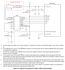
"Both the FET interface module and MSP-GANG430 can supply VCC to the target board (through pin 2). In addition, the FET interface module, MSP-GANG, and MSP-GANG430 have a VCC-sense feature that, if used, requires an alternate connection (pin 4 instead of pin 2). The VCC-sense feature senses the local VCC present on the target board (that is, a battery or other local power supply) and adjusts the output signals accordingly. If the target board is to be powered by a local VCC, then the connection to pin 4 on the JTAG should be made, and not the connection to pin 2. This uses the VCC-sense feature and prevents any contention that might occur if the local on-board VCC were connected to the VCC supplied from the FET interface module, MSP-GANG or the MSP-GANG430. If the VCC-sense feature is not necessary (that is, if the target board is to be powered from the FET interface module, MSP-GANG, or MSP-GANG430), the VCC connection is made to pin 2 on the JTAG header, and no connection is made to pin 4. Figure 2-1 and Figure 2-2 show a jumper block that supports both scenarios of supplying VCC to the target board. If this flexibility is not required, the desired VCC connections may be hard-wired to eliminate the jumper block. Pins 2 and 4 must not be connected at the same time."


