Other Parts Discussed in Thread: ENERGYTRACE,
Hello TI team,
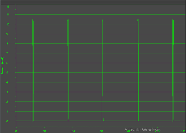
I am working on a TI microcontroller MSP430FR2433, so basically the project involves turning ON a sensor for 2 seconds and then put the MSP430FR2433 in low power mode(LMP3) for 30 seconds. the code is working and the device is entering low power mode but the power consumption is still high (current consumption is 18 micro amps). I am using an external oscillator to get lower power consumption using RTC clock and I see the datasheet says LPM3.5 real-time clock (RTC) counter with 32768-Hz crystal: 730 nA (typical). why is the current consumption so high. expecting atleast around 1 or 2 microamps for LMP3 mode. I have attcahed the code and energytrace below in this thread you can check. Also mentioning removed J11 jumper as well.
#include <msp430.h>

void initGpio(void);

volatile unsigned int secondsCount = 0;
volatile unsigned int blinkCounter = 0;

int main(void)
{
WDTCTL = WDTPW | WDTHOLD; // Stop WDT

initGpio(); // Configure GPIO

// Initialize XT1 32kHz crystal
P2SEL0 |= BIT0 | BIT1; // set XT1 pin as second function
do
{
CSCTL7 &= ~(XT1OFFG | DCOFFG); // Clear XT1 and DCO fault flag
SFRIFG1 &= ~OFIFG;
} while (SFRIFG1 & OFIFG); // Test oscillator fault flag

// Configure RTC
RTCMOD = 32768 - 1; // Set RTC modulo for 1 second
RTCCTL = RTCSS__XT1CLK | RTCSR | RTCPS__1;
RTCCTL |= RTCIE;

// Configure TimerA for 1-second interrupt
TA0CCR0 = 32768 *30 - 1; // Set TimerA period to 1 second
TA0CTL = TASSEL__ACLK | MC__UP; // ACLK, Up mode
TA0CCTL0 = CCIE;
// Enter LPM3.5 mode with interrupts enabled.
__bis_SR_register(LPM3_bits | GIE);
__no_operation();

return 0;
}
#pragma vector=RTC_VECTOR
__interrupt void RTC_ISR(void)
{
switch (__even_in_range(RTCIV, RTCIV_RTCIF))
{
case RTCIV_NONE:
break;
case RTCIV_RTCIF:
secondsCount++; // Increment seconds count
RTCCTL &= ~RTCIF; // Clear RTC interrupt flag
break;
default:
break;
}
}

#pragma vector=TIMER0_A0_VECTOR
__interrupt void TimerA_ISR(void)
{
if(blinkCounter == 1)
{
P1OUT |= BIT0;
}
else
{
P1OUT &= ~BIT0;
}
blinkCounter++;
if(blinkCounter > 30)
{
blinkCounter = 0;
}

// Toggle LED
}
void initGpio(void)
{
P1DIR = 0xFF; P2DIR = 0xFF; P3DIR = 0xFF;
P1REN = 0xFF; P2REN = 0xFF; P3REN = 0xFF;
P1OUT = 0x00; P2OUT = 0x00; P3OUT = 0x00;

// Disable the GPIO power-on default high-impedance mode
// to activate previously configured port settings
PM5CTL0 &= ~LOCKLPM5;
}
thank you,
Best regards,
Pukhraj Singh