Other Parts Discussed in Thread: MSP430G2553
Hello, I was hoping to alter the TI software UART code to make it work
with the second timer A on my device, to ultimately use it with a
bluesmirf while also having a connection to my pc. The problem is I
cannot get much response out of it so I piggy backed the UART on 2.1 and
2.2 to pins 1.1 and 1.2 and am getting no sign of it working on my
computer. I'm not sure if this is because I have done something stupid
when altering the code or it is to do with the state of pin 1.1 and 1.2
messing up the signal. What state should I leave pins 1.1 and 1.2 so
they have no affect on the signal? I was thinking inputs :/
Heres my altered TI code just in case anyone can spot an obvious mistake:
#include "msp430g2553.h"
//------------------------------------------------------------------------------
// Hardware-related definitions
//------------------------------------------------------------------------------
#define UART_TXD 0x02 // TXD on P1.1 (Timer0_A.OUT0)
#define UART_RXD 0x04 // RXD on P1.2 (Timer0_A.CCI1A)
//------------------------------------------------------------------------------
// Conditions for 9600 Baud SW UART, SMCLK = 1MHz
//------------------------------------------------------------------------------
#define UART_TBIT_DIV_2 (1000000 / (9600 * 2))
#define UART_TBIT (1000000 / 9600)
//------------------------------------------------------------------------------
// Global variables used for full-duplex UART communication
//------------------------------------------------------------------------------
unsigned int txData; // UART internal variable for TX
unsigned char rxBuffer; // Received UART character
//------------------------------------------------------------------------------
// Function prototypes
//------------------------------------------------------------------------------
void TimerA_UART_init(void);
void TimerA_UART_tx(unsigned char byte);
void TimerA_UART_print(char *string);
//------------------------------------------------------------------------------
// main()
//------------------------------------------------------------------------------
void main(void)
{
WDTCTL = WDTPW + WDTHOLD; // Stop watchdog timer
DCOCTL = 0x00; // Set DCOCLK to 1MHz
BCSCTL1 = CALBC1_1MHZ;
DCOCTL = CALDCO_1MHZ;
P2OUT = 0x00; // Initialize all GPIO
P2SEL = UART_TXD + UART_RXD; // Timer function for TXD/RXD pins
P2DIR = 0xFF & ~UART_RXD; // Set all pins but RXD to output
__enable_interrupt();
TimerA_UART_init(); // Start Timer_A UART
//TimerA_UART_tx(0xFF);
TimerA_UART_print("G2xx2 TimerA UART\r\n");
TimerA_UART_print("READY.\r\n");
for (;;)
{
// Wait for incoming character
__bis_SR_register(LPM0_bits);
// Update board outputs according to received byte
if (rxBuffer & 0x01) P1OUT |= 0x01; else P1OUT &= ~0x01; // P1.0
if (rxBuffer & 0x02) P1OUT |= 0x08; else P1OUT &= ~0x08; // P1.3
if (rxBuffer & 0x04) P1OUT |= 0x10; else P1OUT &= ~0x10; // P1.4
if (rxBuffer & 0x08) P1OUT |= 0x20; else P1OUT &= ~0x20; // P1.5
if (rxBuffer & 0x10) P1OUT |= 0x40; else P1OUT &= ~0x40; // P1.6
if (rxBuffer & 0x20) P1OUT |= 0x80; else P1OUT &= ~0x80; // P1.7
if (rxBuffer & 0x40) P2OUT |= 0x40; else P2OUT &= ~0x40; // P2.6
if (rxBuffer & 0x80) P2OUT |= 0x80; else P2OUT &= ~0x80; // P2.7
// Echo received character
TimerA_UART_tx(rxBuffer);
}
}
//------------------------------------------------------------------------------
// Function configures Timer_A for full-duplex UART operation
//------------------------------------------------------------------------------
void TimerA_UART_init(void)
{
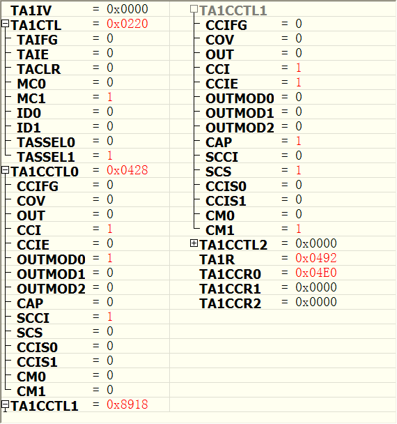
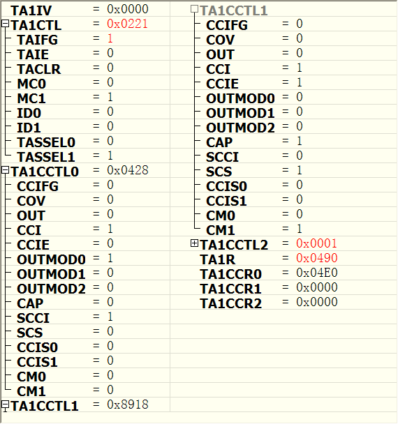
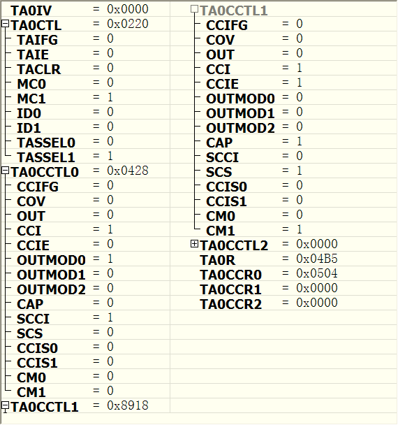
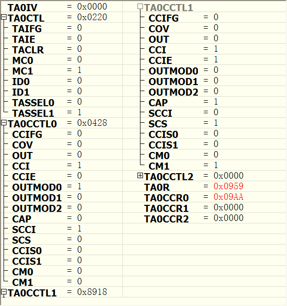
TA1CCTL0 = OUT; // Set TXD Idle as Mark = '1'
TA1CCTL1 = SCS + CM1 + CAP + CCIE; // Sync, Neg Edge, Capture, Int
TA1CTL = TASSEL_2 + MC_2; // SMCLK, start in continuous mode
}
//------------------------------------------------------------------------------
// Outputs one byte using the Timer_A UART
//------------------------------------------------------------------------------
void TimerA_UART_tx(unsigned char byte)
{
while (TA1CCTL0 & CCIE); // Ensure last char got TX'd
TA1CCR0 = TAR; // Current state of TA counter
TA1CCR0 += UART_TBIT; // One bit time till first bit
TA1CCTL0 = OUTMOD0 + CCIE; // Set TXD on EQU0, Int
txData = byte; // Load global variable
txData |= 0x100; // Add mark stop bit to TXData
txData <<= 1; // Add space start bit
}
//------------------------------------------------------------------------------
// Prints a string over using the Timer_A UART
//------------------------------------------------------------------------------
void TimerA_UART_print(char *string)
{
while (*string) {
TimerA_UART_tx(*string++);
}
}
//------------------------------------------------------------------------------
// Timer_A UART - Transmit Interrupt Handler
//------------------------------------------------------------------------------
#pragma vector = TIMER1_A0_VECTOR
__interrupt void Timer1_A0_ISR(void)
{
static unsigned char txBitCnt = 10;
TA1CCR0 += UART_TBIT; // Add Offset to CCRx
if (txBitCnt == 0) { // All bits TXed?
TA1CCTL0 &= ~CCIE; // All bits TXed, disable interrupt
txBitCnt = 10; // Re-load bit counter
}
else {
if (txData & 0x01) {
TA1CCTL0 &= ~OUTMOD2; // TX Mark '1'
}
else {
TA1CCTL0 |= OUTMOD2; // TX Space '0'
}
txData >>= 1;
txBitCnt--;
}
}
//------------------------------------------------------------------------------
// Timer_A UART - Receive Interrupt Handler
//------------------------------------------------------------------------------
#pragma vector = TIMER1_A1_VECTOR
__interrupt void Timer1_A1_ISR(void)
{
static unsigned char rxBitCnt = 8;
static unsigned char rxData = 0;
switch (__even_in_range(TA1IV, TA1IV_TAIFG)) { // Use calculated branching
case TA1IV_TACCR1: // TACCR1 CCIFG - UART RX
TA1CCR1 += UART_TBIT; // Add Offset to CCRx
if (TA1CCTL1 & CAP) { // Capture mode = start bit edge
TA1CCTL1 &= ~CAP; // Switch capture to compare mode
TA1CCR1 += UART_TBIT_DIV_2; // Point CCRx to middle of D0
}
else {
rxData >>= 1;
if (TA1CCTL1 & SCCI) { // Get bit waiting in receive latch
rxData |= 0x80;
}
rxBitCnt--;
if (rxBitCnt == 0) { // All bits RXed?
rxBuffer = rxData; // Store in global variable
rxBitCnt = 8; // Re-load bit counter
TA1CCTL1 |= CAP; // Switch compare to capture mode
__bic_SR_register_on_exit(LPM0_bits); // Clear LPM0 bits from 0(SR)
}
}
break;
}
}
//------------------------------------------------------------------------------