Hi,
I want to see the digital conversion value and processing time of AD conversion.
Where should I check?...
MCU is a topic part, and the module is ΣΔ SD24_B Modulator.
Please tell me.
Thank you
This thread has been locked.
If you have a related question, please click the "Ask a related question" button in the top right corner. The newly created question will be automatically linked to this question.
Hi,
I want to see the digital conversion value and processing time of AD conversion.
Where should I check?...
MCU is a topic part, and the module is ΣΔ SD24_B Modulator.
Please tell me.
Thank you
Hi, toshiharu
You can use start a timer before the ADC conversion.
Reading the timer's counter value before and after ADC conversion to get the processing time in the form of timer cycles.
Another way is using oscillograph to watch the GPIO toggle before and after ADC conversion.
Regards,
Helic
Hi, Helic
Thank you for letting me know.
I'm still not good at programming, so I'd appreciate it if you could tell me.
I understand how to use an oscillograph. thank you.
Regarding starting the timer, is it correct to define the timer function before starting AD conversion?
After that, the obtained processing time is read as the value of the timer function specified in the Expression Tab?
Relatedly, I would like to ask you about MSPware.
This sample code for SD24B has content that allows you to obtain integers (sd24b_05, sd24b_06), so when you try to debug it, it stops at the while statement.
I would appreciate it if you could let me know if you know.
If you don't know, please contact TI's support center.
Thank you.
Toshiharu
Hi, toshiharu
Regarding starting the timer, is it correct to define the timer function before starting AD conversion?
Yes, start the timer, read the timer's counter value before and after your test code.
The difference between two reads is the running time for N timer cycles.
it stops at the while statement.
I don't quite know what you mean.
If you set a breakpoint at line105 or line109, you can see the result(results) when it stops.
You can start timer before main while and read counter value before start ADC and read counter before breakpoint.
For GPIO calculation, it is easier. Please refer to the sample code MSP430F677x_P1_0x.c
Regards,
Helic
Hi, Helic
Thank you for letting me know.
I understand about the timer function. If I don't understand, I'll ask another question.
If you set a breakpoint at line105 or line109, you can see the result(results) when it stops.
You can start timer before main while and read counter value before start ADC and read counter before breakpoint.
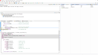
I'm sorry. I'll post an image.
As shown in the image, it stops at "__bis_SR_register(LPM0_bits | GIE);" in the while statement.
If you look to the left of there, you will see "MSP430 - Debug call Stack".
The program is progressing with "Step Into".
If you need further information, please let me know.
Thank you
Toshiharu

Hi, toshiharu
Set a breakpoint on line 22 or line 25, both is OK, then click run from start of main, waiting for breakpoint will be fine.
Between entering LPM0 and exiting LPM0 in ADC interrupts, step into cannot be used.
Regards,
Helic
Hi, Helic
Thank you for letting me know.
Sorry for the late reply.
I included time.h and defined start and end with time_t. We also defined a double type diff = difftime(start,end).
I think this puts start and end in the while statement, but where should I put the code for diff?
Regards,
Toshiharu

Hi, toshiharu
Read timer counter value before ADC start conversion as timerValStart.
Read timer counter value after ADC conversion finished, which can be before the breakpoint as timerValStop.
while(1) {
    TimerValStart = Read Timer value;
    SD24B = ADC start;
    Enter_LPM0();
    NOP();
    NOP();
    TimerValStop = Read Timer value;
    SD24RunningTime = Calculate the exe time;
    NOP(); with breakpoint;
}
Or you can try GPIO toggle, this way is easier.
Regards,
Helic
**Attention** This is a public forum