This thread has been locked.

If you have a related question, please click the "Ask a related question" button in the top right corner. The newly created question will be automatically linked to this question.

LP-MSPM0G3507: Transferring data from Rx buffer to the frame (created by us)

Part Number: LP-MSPM0G3507
Other Parts Discussed in Thread: MSPM0G3507

Hi, in my application I am using the BQ79600 as a bridge device and BQ79656 as a cell monitoring device, and LP-MSPM0G3507 to control and transfer the data using the UART. 

I used example code for BQ79600 UART, in that example there is a response frame, which will collect all data coming from the bridge device.

But I checked the data is coming from Tx pin of BQ79600 which is connected to Rx pin of LP-MSPM0G3507, and the Rx buffer is also getting the data, but it is not transferring to the response frame.

Please help me regarding the same.

Thanks and Regards

Abhaya Raj Mishra

  • Hi, Abhaya

    Make sure M0G had send the correct read command in form of correct Frame Structure.

    Follow the instruction shown in Document: 7.3.2:

    BQ79600-Q1 Automotive SPI/UART Communication Interface with Functional Safety datasheet (Rev. A)

    Regards,

    Helic

  • Hi, I have used same sample code commands only, it is perfectly sending the signals to wake devices and all, but the issue is occurring in Rx side.

  • do { channel = 0; currentBoard = 0; delayus(192+5*TOTALBOARDS); ReadReg(0, VCELL16_HI+(16-ACTIVECHANNELS)*2, response_frame, ACTIVECHANNELS*2, 0, FRMWRT_STK_R); ReadReg(0, GPIO1_HI+(8-ACTIVECHANNELS)*2, response_frame_T, ACTIVECHANNELS*2, 0, FRMWRT_STK_R); /* * *********************************************** * NOTE: SOME COMPUTERS HAVE ISSUES RECEIVING * A LARGE AMOUNT OF DATA VIA printf STATEMENTS. * THE FOLLOWING PRINTOUT OF THE RESPONSE DATA * IS NOT GUARANTEED TO WORK ON ALL SYSTEMS. * *********************************************** */ printf("\n"); //start with a newline to add some extra spacing between each loop //only read/print the base device's data if there is no bridge device for(currentBoard=0; currentBoard<( BRIDGEDEVICE==1 ? TOTALBOARDS-1 : TOTALBOARDS); currentBoard++) { printf("BOARD %d:\t",TOTALBOARDS-currentBoard-1); //print the data from each active channel (2 bytes each channel) for(channel=0; channel<(ACTIVECHANNELS*2); channel+=2) { int boardByteStart = (ACTIVECHANNELS*2+6)*currentBoard; uint16 rawData = (response_frame[boardByteStart+channel+4] << 8) | response_frame[boardByteStart+channel+5]; float cellVoltage = rawData*0.00019073; //rawData*VLSB_ADC printf("%f\t", cellVoltage); } printf("\n"); //newline per board } }while(1);

  • Hi, 

    Hi, are you using printf for debugging? make sure it works well.

    Or a logic analyzer or watch rx_buf in debug mode will help.

    You can use Insert - </>Code below to insert a block of codes.

    Regards,

    Helic

  • Ya, I'm using printf for printing the voltage values which should come in response frame, but it is printing 0  only.

    I've checked with Logic analyzer as well, the BQ7900 is perfectly sending some values, and Rx buffer is also getting updated continuously. 

     do
        {
            channel = 0;
            currentBoard = 0;
            delayus(192+5*TOTALBOARDS);
            ReadReg(0, VCELL16_HI+(16-ACTIVECHANNELS)*2, response_frame, ACTIVECHANNELS*2, 0, FRMWRT_STK_R);
            ReadReg(0, GPIO1_HI+(8-ACTIVECHANNELS)*2, response_frame_T, ACTIVECHANNELS*2, 0, FRMWRT_STK_R);
            /*
             * ***********************************************
             * NOTE: SOME COMPUTERS HAVE ISSUES RECEIVING
             * A LARGE AMOUNT OF DATA VIA printf STATEMENTS.         * THE FOLLOWING PRINTOUT OF THE RESPONSE DATA
             * IS NOT GUARANTEED TO WORK ON ALL SYSTEMS.
             * ***********************************************
            */
    
            printf("\n"); //start with a newline to add some extra spacing between each loop
            //only read/print the base device's data if there is no bridge device
            for(currentBoard=0; currentBoard<( BRIDGEDEVICE==1 ? TOTALBOARDS-1 : TOTALBOARDS); currentBoard++)
            {
                printf("BOARD %d:\t",TOTALBOARDS-currentBoard-1);
                //print the data from each active channel (2 bytes each channel)
                for(channel=0; channel<(ACTIVECHANNELS*2); channel+=2)
                {
                    int boardByteStart = (ACTIVECHANNELS*2+6)*currentBoard;
                    uint16 rawData = (response_frame[boardByteStart+channel+4] << 8) | response_frame[boardByteStart+channel+5];
                    float cellVoltage = rawData*0.00019073; //rawData*VLSB_ADC
                    printf("%f\t", cellVoltage);
                }
    
    
                printf("\n"); //newline per board
            }
    
        }while(1);

  • Hi, 

    the BQ7900 is perfectly sending some values

    Check whether this return value is correct. At the same time, check the M0 send read command is correct via Logic analyzer.
    need to find out which part is working abnormally.

    Regards,

    Helic

  • If you are using an RX interrupt, put a breakpoint in the interrupt.

  • Ok I'll try that too 

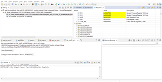
  • Hi, This over run register is setting to 11,

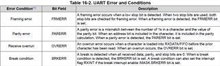
    OVRERR 1 - SET UART Receive Overrun Error Writing to this bit has no effect. The flag is cleared by writing 1 to the OVRERR bit in the UART EVENT ICLR register. In case of a receive FIFO overflow, the FIFO contents remain valid because no further data is written when the FIFO is full. Only the contents of the shift register are overwritten. The CPU must read the data in order to empty the FIFO.

    Can you please let me know the solution.

  • Hi, 

    A OVRERR = 1 means there is data in Rx FIFO need to read out and there is already data that has been discarded because the FIFO is full.

    Please refer to this code example in SDK: 

    C:\ti\mspm0_sdk_1_20_01_06\examples\nortos\LP_MSPM0G3507\driverlib\uart_rw_multibyte_fifo_poll

    Or the web link:

    uart_rw_multibyte_fifo_poll

    Regards,

    Helic

  • I tried with this example code, but this example code might have some problem, it is not implementing. 

    Can you please check this on your end once.

  • Hi, 

    I use this example a lot. Didn't find any problem.

    but this example code might have some problem, it is not implementing. 

    What kind of issues do you encounter?

    Or a logic analyzer or watch rx_buf in debug mode will help.

    I still recommend that try to observe the UART Tx and Rx data using debug mode or using logic analyzer.

    Regards,

    Helic

  • Hi, 

    Please follow the readme and readme - example usage of code example.

    Update the jumpers to connect RX and TX between two UART devices.

    uart_rw_multibyte_fifo_poll

    This example shows how to communicate with other device via UART.

    But I checked the data is coming from Tx pin of BQ79600 which is connected to Rx pin of LP-MSPM0G3507, and the Rx buffer is also getting the data, but it is not transferring to the response frame.

    Check if this Rx buffer is correct and why not send response by add breakpoint at transmission function in debug mode.

    Regards,

    Helic

  • I checked with the break points 

    It is in loop here 

    __STATIC_INLINE bool DL_UART_isRXFIFOEmpty(UART_Regs *uart)
    {
    return ((uart->STAT & UART_STAT_RXFE_MASK) == UART_STAT_RXFE_SET);
    }

  • Hi, 

    M0 is still waiting for new data coming from UART.

    After stuck here, you need to check the reason, check the Receive buffer.

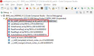
    In the CCS Debug window, check for function nesting at breakpoint like figure below, this is helpful to find out which function is calling isRXFIFOEmpty.

    Refer to datasheet 7.3.2 to check the data between M0 and BQ.

    BQ79600-Q1 Automotive SPI/UART Communication Interface with Functional Safety datasheet (Rev. A)

    Regards,

    Helic

  • Ok, but at the same time, the OVRERR 1 - SET, this is also happening. 


  • Hi, 

    Did you see any data on M0's Rx port using Logic analyzer?

    By the way,

    If the program is waiting for receiving data, the code should be:

    while(DL_UART_isRXFIFOEmpty(UART0));
    
    UARTRxBuffer = UART0.RXDATA.

    Regards,

    Helic

  • Ok, I'll try this as well.

    But can you please let me know about the error I'm getting on internal loopback mode of the UART

  • Hi, 

    Functions declared as inline may cause this.

    These kind of functions often have only a few lines of codes and are called very often.

    This is not an error.

    You know that the program is performing a delay function is OK, and if you are interested, you can check out the disassembly.

    Regards,

    Helic

  • So, what need to be done for this?

  • Nothing need to do.

  • but this loopback ex code is not working. 

    Directly this is popping up when we start debug and run it.

  • but this loopback ex code is not working. 

    This internal loopback example code will toggle LED if succeed.

    After you click start button in debug mode, you can see red LED toggles very fast.

    Every red LED toggle means is UART send data is same as a UART receive data, which mean it's worked.

    Directly this is popping up when we start debug and run it.

    It stopped at here? Please show me your debug window when popping up.

    ---

    If you want to test UART communicate with another device, try external loopback example.

    Regards,

    Helic

  • Ok, and led is also not toggling. 

  • And related to previous query, here are the logic analyzer data, and the RX buffer and interrupt screenshot.

    In the Logic analyzer image channel0 is TX data and channle1 is Rx data. It is the same data where the loop is sticking.

    Logic analyzer: 

    Rx data and buffer and interrupt: 

  • I cannot get any useful information from your logic analyzer screenshot

  • HI, 

    I recommend that you use debug to see if the data in the send and receive function is correct.

    From your screenshot, it should be AutoAddress(). Check these function to find the Tx and Rx buffer.

    At the same time, a logic analyzer is used to capture the Tx and Rx data line.

    Regards,

    Helic

  • Inside AutoAddress() there are some readreg() instructions are there, 

    This code is from you example code only of BQ7900 UART sample code.

    In this the first readreg statement is implementing but in 2nd one it is stuck.

  • Hi, for baudrate 1Mbps, for UART, what should be the clk frequency?

    can you please tell me.

  • Hi, 

    You need keep as below:

        Baud Rate * Oversampling <= Clock Source

    If default Oversampling = 16x and Baud Rate = 1M.

    Clock Source should >= 16 MHz. 32MHz is recommended.

    And you should also keep Calculated Error (%) <= 1%.

    Regards,

    Helic

  • Ya I'm using 32MHz, with oversampling 16.

  • void AutoAddress()
    {
        //DUMMY WRITE TO SNCHRONIZE ALL DAISY CHAIN DEVICES DLL (IF A DEVICE RESET OCCURED PRIOR TO THIS)
        WriteReg(0, OTP_ECC_DATAIN1, 0X00, 1, FRMWRT_STK_W);   // I'm changing it to all write from stk_w, tried did't worked
        WriteReg(0, OTP_ECC_DATAIN2, 0X00, 1, FRMWRT_STK_W);
        WriteReg(0, OTP_ECC_DATAIN3, 0X00, 1, FRMWRT_STK_W);
        WriteReg(0, OTP_ECC_DATAIN4, 0X00, 1, FRMWRT_STK_W);
        WriteReg(0, OTP_ECC_DATAIN5, 0X00, 1, FRMWRT_STK_W);
        WriteReg(0, OTP_ECC_DATAIN6, 0X00, 1, FRMWRT_STK_W);
        WriteReg(0, OTP_ECC_DATAIN7, 0X00, 1, FRMWRT_STK_W);
        WriteReg(0, OTP_ECC_DATAIN8, 0X00, 1, FRMWRT_STK_W);
    
        //ENABLE AUTO ADDRESSING MODE
        WriteReg(0, CONTROL1, 0X01, 1, FRMWRT_ALL_W);
    
        //SET ADDRESSES FOR EVERY BOARD
        for(currentBoard=0; currentBoard<TOTALBOARDS; currentBoard++)
        {
            WriteReg(0, DIR0_ADDR, currentBoard, 1, FRMWRT_ALL_W);
        }
    
        //BROADCAST WRITE TO SET ALL DEVICES AS STACK DEVICE
        WriteReg(0, COMM_CTRL, 0x02, 1, FRMWRT_ALL_W);
    
        //SET THE HIGHEST DEVICE IN THE STACK AS BOTH STACK AND TOP OF STACK
        //WriteReg(TOTALBOARDS-1, COMM_CTRL, 0x03, 1, FRMWRT_SGL_W);
        // insted of this Kartik code
        if(TOTALBOARDS==1) //if there's only 1 board, it's the base AND top of stack, so change it to those
         {
             WriteReg(0, COMM_CTRL, 0x01, 1, FRMWRT_SGL_W);
         }
         else //otherwise set the base and top of stack individually
         {
             WriteReg(0, COMM_CTRL, 0x00, 1, FRMWRT_SGL_W);
             WriteReg(TOTALBOARDS-1, COMM_CTRL, 0x03, 1, FRMWRT_SGL_W);
         }
    
        //SYNCRHONIZE THE DLL WITH A THROW-AWAY READ
        // I tried to change this for the single read configuration (didn't worked) - Abhaya raj mishra
        ReadReg(0, OTP_ECC_DATAIN1, autoaddr_response_frame, 1, 0, FRMWRT_STK_R);    // changing all to all read from stk_r, tried did't worked
        ReadReg(0, OTP_ECC_DATAIN2, autoaddr_response_frame, 1, 0, FRMWRT_STK_R);
        ReadReg(0, OTP_ECC_DATAIN3, autoaddr_response_frame, 1, 0, FRMWRT_STK_R);
        ReadReg(0, OTP_ECC_DATAIN4, autoaddr_response_frame, 1, 0, FRMWRT_STK_R);
        ReadReg(0, OTP_ECC_DATAIN5, autoaddr_response_frame, 1, 0, FRMWRT_STK_R);
        ReadReg(0, OTP_ECC_DATAIN6, autoaddr_response_frame, 1, 0, FRMWRT_STK_R);
        ReadReg(0, OTP_ECC_DATAIN7, autoaddr_response_frame, 1, 0, FRMWRT_STK_R);
        ReadReg(0, OTP_ECC_DATAIN8, autoaddr_response_frame, 1, 0, FRMWRT_STK_R);
    
        //OPTIONAL: read back all device addresses
    //    for(currentBoard=0; currentBoard<TOTALBOARDS; currentBoard++)
    //    {
    //        ReadReg(currentBoard, DIR0_ADDR, autoaddr_response_frame, 1, 0, FRMWRT_SGL_R);
    //    }
    //
        //OPTIONAL: read register address 0x2001 and verify that the value is 0x14
    //    ReadReg(0, 0x2001, autoaddr_response_frame, 1, 0, FRMWRT_SGL_R);
    // ************
        //RESET ANY COMM FAULT CONDITIONS FROM STARTUP
         WriteReg(0, FAULT_RST2, 0x03, 1, FRMWRT_ALL_W);
    
        return;
    }
    
    //**************************
    //END AUTO ADDRESS SEQUENCE
    //**************************
    
    
    //************************
    //WRITE AND READ FUNCTIONS
    //************************
    
    //FORMAT WRITE DATA, SEND TO
    //BE COMBINED WITH REST OF FRAME
    int WriteReg(BYTE bID, uint16 wAddr, uint64 dwData, BYTE bLen, BYTE bWriteType) {
        // device address, register start address, data bytes, data length, write type (single, broadcast, stack)
        memset(bBuf,0,sizeof(bBuf));
        switch (bLen) {
        case 1:
            bBuf[0] = dwData & 0x00000000000000FF;
            bRes = WriteFrame(bID, wAddr, bBuf, 1, bWriteType);
            break;
        case 2:
            bBuf[0] = (dwData & 0x000000000000FF00) >> 8;
            bBuf[1] = dwData & 0x00000000000000FF;
            bRes = WriteFrame(bID, wAddr, bBuf, 2, bWriteType);
            break;
        case 3:
            bBuf[0] = (dwData & 0x0000000000FF0000) >> 16;
            bBuf[1] = (dwData & 0x000000000000FF00) >> 8;
            bBuf[2] = dwData & 0x00000000000000FF;
            bRes = WriteFrame(bID, wAddr, bBuf, 3, bWriteType);
            break;
        case 4:
            bBuf[0] = (dwData & 0x00000000FF000000) >> 24;
            bBuf[1] = (dwData & 0x0000000000FF0000) >> 16;
            bBuf[2] = (dwData & 0x000000000000FF00) >> 8;
            bBuf[3] = dwData & 0x00000000000000FF;
            bRes = WriteFrame(bID, wAddr, bBuf, 4, bWriteType);
            break;
        case 5:
            bBuf[0] = (dwData & 0x000000FF00000000) >> 32;
            bBuf[1] = (dwData & 0x00000000FF000000) >> 24;
            bBuf[2] = (dwData & 0x0000000000FF0000) >> 16;
            bBuf[3] = (dwData & 0x000000000000FF00) >> 8;
            bBuf[4] = dwData & 0x00000000000000FF;
            bRes = WriteFrame(bID, wAddr, bBuf, 5, bWriteType);
            break;
        case 6:
            bBuf[0] = (dwData & 0x0000FF0000000000) >> 40;
            bBuf[1] = (dwData & 0x000000FF00000000) >> 32;
            bBuf[2] = (dwData & 0x00000000FF000000) >> 24;
            bBuf[3] = (dwData & 0x0000000000FF0000) >> 16;
            bBuf[4] = (dwData & 0x000000000000FF00) >> 8;
            bBuf[5] = dwData & 0x00000000000000FF;
            bRes = WriteFrame(bID, wAddr, bBuf, 6, bWriteType);
            break;
        case 7:
            bBuf[0] = (dwData & 0x00FF000000000000) >> 48;
            bBuf[1] = (dwData & 0x0000FF0000000000) >> 40;
            bBuf[2] = (dwData & 0x000000FF00000000) >> 32;
            bBuf[3] = (dwData & 0x00000000FF000000) >> 24;
            bBuf[4] = (dwData & 0x0000000000FF0000) >> 16;
            bBuf[5] = (dwData & 0x000000000000FF00) >> 8;
            bBuf[6] = dwData & 0x00000000000000FF;
            bRes = WriteFrame(bID, wAddr, bBuf, 7, bWriteType);
            break;
        case 8:
            bBuf[0] = (dwData & 0xFF00000000000000) >> 56;
            bBuf[1] = (dwData & 0x00FF000000000000) >> 48;
            bBuf[2] = (dwData & 0x0000FF0000000000) >> 40;
            bBuf[3] = (dwData & 0x000000FF00000000) >> 32;
            bBuf[4] = (dwData & 0x00000000FF000000) >> 24;
            bBuf[5] = (dwData & 0x0000000000FF0000) >> 16;
            bBuf[6] = (dwData & 0x000000000000FF00) >> 8;
            bBuf[7] = dwData & 0x00000000000000FF;
            bRes = WriteFrame(bID, wAddr, bBuf, 8, bWriteType);
            break;
        default:
            break;
        }
        return bRes;
    }
    
    
    int WriteFrame(BYTE bID, uint16 wAddr, BYTE * pData, BYTE bLen, BYTE bWriteType) {
        int bPktLen = 0;
        uint8 * pBuf = pFrame;
        memset(pFrame, 0x7F, sizeof(pFrame));
        *pBuf++ = 0x80 | (bWriteType) | ((bWriteType & 0x10) ? bLen - 0x01 : 0x00); //Only include blen if it is a write; Writes are 0x90, 0xB0, 0xD0
        if (bWriteType == FRMWRT_SGL_R || bWriteType == FRMWRT_SGL_W)
        {
            *pBuf++ = (bID & 0x00FF);
        }
        *pBuf++ = (wAddr & 0xFF00) >> 8;
        *pBuf++ = wAddr & 0x00FF;
    
        while (bLen--)
            *pBuf++ = *pData++;
    
        bPktLen = pBuf - pFrame;
    
        wCRC2 = CRC16(pFrame, bPktLen);
        *pBuf++ = wCRC2 & 0x00FF;
        *pBuf++ = (wCRC2 & 0xFF00) >> 8;
        bPktLen += 2;
        //THIS SEEMS to occasionally drop bytes from the frame. Sometimes is not sending the last frame of the CRC.
        //(Seems to be caused by stack overflow, so take precautions to reduce stack usage in function calls)
    
        sendData(bPktLen, pFrame);
    
        return bPktLen;
    }
    
    void sendData(uint32 length,uint8 *data)
    {
        uint8_t txPacket[10] = {};
            delayus(500);
            for(int i = 0; i< length; i++){
                while (!DL_UART_Main_isRXFIFOEmpty(UART_0_INST));
                DL_UART_Main_transmitDataBlocking(UART_0_INST, *data);
                data++;
            }
       /* Wait until all bytes have been transmitted and the TX FIFO is empty */
            while (DL_UART_Main_isBusy(UART_0_INST));
    
    }
    
    
    int ReadReg(BYTE bID, uint16 wAddr, BYTE * pData, BYTE bLen, uint32 dwTimeOut, BYTE bWriteType){
        //GENERATE READ COMMAND FRAME AND THEN WAIT FOR RESPONSE DATA (INTERRUPT MODE FOR SCIRX)
        // device address, register start address, byte frame pointer to store data, data length, read type (single, broadcast, stack)
        //DL_UART_disableInterrupt(UART_0_INST,DL_UART_INTERRUPT_RX);
        bRes = 0;
        count = 1000000; //timeout after this many attempts
    
        if (bWriteType == FRMWRT_SGL_R) {
            ReadFrameReq(bID, wAddr, bLen, bWriteType);
            memset(&pData, 0, sizeof(pData));
            DL_UART_enableInterrupt(UART_0_INST,DL_UART_INTERRUPT_RX);
            bRes = bLen + 6;
    
        } else if (bWriteType == FRMWRT_STK_R) {
            bRes = ReadFrameReq(bID, wAddr, bLen, bWriteType);
            memset(&pData, 0, sizeof(pData));
            DL_UART_enableInterrupt(UART_0_INST,DL_UART_INTERRUPT_RX);
            bRes = (bLen + 6) * (TOTALBOARDS - 1);
    
        } else if (bWriteType == FRMWRT_ALL_R) {
            bRes = ReadFrameReq(bID, wAddr, bLen, bWriteType);
            memset(&pData, 0, sizeof(pData));
            DL_UART_enableInterrupt(UART_0_INST,DL_UART_INTERRUPT_RX);
            bRes = (bLen + 6) * TOTALBOARDS;
    
        } else {
            bRes = 0;
        }
    
    //    //CHECK IF CRC IS CORRECT
    //    for(crc_i=0; crc_i<bRes; crc_i+=(bLen+6))
    //    {
    //        if(CRC16(&pData[crc_i], bLen+6)!=0)
    //        {
    //            printf("BAD CRC\n");
    //        }
    //    }
    
        return bRes;
    
    }
    
    int ReadFrameReq(BYTE bID, uint16 wAddr, BYTE bByteToReturn, BYTE bWriteType) {
        bReturn = bByteToReturn - 1;
    
        if (bReturn > 127)
            return 0;
    
        return WriteFrame(bID, wAddr, &bReturn, 1, bWriteType);
    }

    This is the code for autoaddress please check once, 

    because that Rx overrun error is not able to resolve.

  • Hi, 

    You need to dig into this code by yourself and find out why this code example is stop receiving data and generate a OVERRUN error.

    Here is my suggestions:

        Which communication command cause this.

        Before the Error generated, what data had been send to BQ and received from BQ.

        Depending on these data, Why it stuck here?

    Regards,

    Helic

**Attention** This is a public forum