


Part Number: EVM430-FR6043
Hi!
I'm exploring the EVM430-FR6043 reference design and would like to replicate the MCU and the analog part in my own design.
Upon studying the reference designs crystal oscillators I noticed that the load capacitors for HFXT (designator Y1) and USSXT (designator Y3) had been sized differently than I would have assumed. I would like to understand why have these oscillator and load capacitor combinations been selected in order to make sure that I'm not missing something critical.
1) USSXTAL
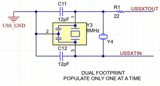
In the reference design there are two options for USSXTAL; AWSCR-8.00CV-T (designator Y3) and ABLS-8.000MHZ-B4-T (designator Y4), for which there are load 12pF load capacitors (designators C11 and C12) in place. On my EVM430-FR6043 evaluation board I can see that Y3 is chosen to be populated along with the load capacitors.
My first question is why is this? AWSCR-8.00CV-T seems to have integrated capacitors so why are C11 and C12 assembled? AWSCR-8.00CV-T (Y3) has capacitance of 22pF, while the optional ABLS-8.000MHZ-B4-T (Y4) has 18pF. My expectation is that C11 and C12 would only have been needed if Y4 was populated instead of Y3.
2) HFXTAL
The HFXTAL is ABM3-8.000MHZ-D2Y-T (designator Y1) and has load capacitance of 18pF. Along with it there are two load capacitors C15 and C16, both 12pF, in place. My rule of thumb has been to size the capacitors accoring to Cx = 2 x (Cload - Cstray), where Cx is external load capacitor, Cload is the load capacitance of the crystal oscillator and Cstray is the stray capacitance. I would assume the Cstray to be in the order of 3pF - 5pF. However, calculating the load capacitors this way, I get 2 x (18pF - 5pF) = 26pF to 30 pF (depending on the assumed stray capacitance). Both of these are of course way off the 12pF used in the EVM430-FR6043 development board. Why is this combination of crystal oscillator and load capacitors selected?

Thank you for your insight.

