This thread has been locked.

If you have a related question, please click the "Ask a related question" button in the top right corner. The newly created question will be automatically linked to this question.

MSP430F5510: Total worst case currents from 3.3V and 5V-USB

Part Number: MSP430F5510


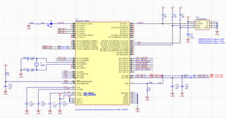
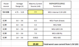
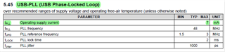
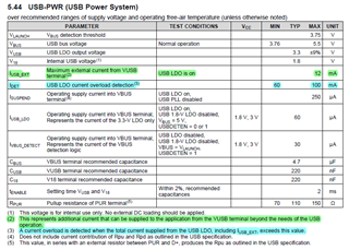
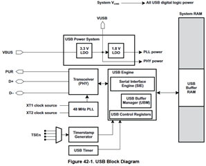
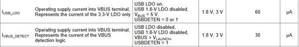
I am trying to estimate the total worst case current during USB operation for 3.3V from internal LDO and 5V from USB connected to pin Vbus of MCU. Two attachments below show the circuit with the MCU and table for listing maximum current consumed by each MCU function.   

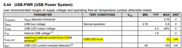
  1. Could you please estimate total worst case currents for 3.3V from internal LDO (excluding external 12 mA) and 5V from external USB-host? 
  2. What are maximum allowable currents for 3.3V LDO and 5V from external USB-host? 

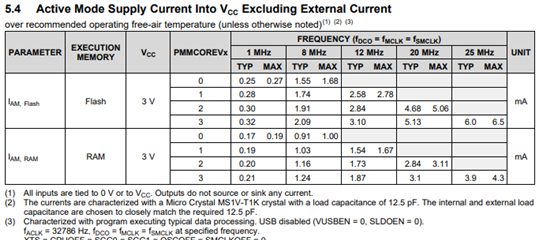
I listed individual maximum current for each MCU function on the table below. If I missed, please provide a list of other currents to be considered. 

Thanks,

Albert


  • Hi Albert,

    I think you are getting confused on the specifications.

    First, as shown in the table below, the Flash specification is the device current when the CPU is executing code read from FLASH memory.  The specification for RAM is when CPU is executing code read from RAM. They won't occur at the same time so you can't just add the two separate currents together.  BTW, typically code is almost always executed from FLASH so use the 6.5mA value.  This also includes any PLL current.

    Next, the USB LDO spec shown below means you shouldn't draw more than 12mA from the output.  The LDO gets it power directly from VBUS and creates a +3.3v output.  This output can drive both the MSP430 CPU and any additional circuitry, provided you don't exceed the 12mA   So if you know the MSP will draw 6.5mA(max), then the LDO is capable of supplying an additional 5.5mA.  

    So to answer your question, if you use the internal +3.3v LDO to supply power only the MSP430, then the maximum current for the entire device will be 6.5mA.  If, however, you have additional circuitry, like an LED driver IC and LEDs which also derives power from this LD, then you will have to add that additional current on top of the 6.5mA.

    Does this help answer your question? 

  • Hi Dennis, 

    Thank you for your quick response.  Greatly appreciate it. 

    Your explanation with data sheet partially helps.  Can we chat tomorrow (Thursday)?  If yes, what time(s)?   In the meantime, I have some questions as follow. 

    1-) Ok, I understand for not adding Flash and RAM currents together.  I'll use 6.5 mA for Flash current.  For clarification, do you mean this 6.5 mA also includes USB PLL current?  Per spec below, the operating supply current for USB-PLL shows 7 mA.  This seems a separate current, not included n Flash current 6.5mA.  Isn't it correct? 


    2-) Per spec below, the note 2 (green highlighted) says: the Maximum external current 12 mA represents additional current that can be supplied to the application from the Vusb terminal (LDO output) beyond the needs of the USB operation. This sounds like the 12 mA current does not include the currents for MSP430 CPU and USB operations.  Am I interpreting incorrectly? .

    3-) To confirm my understanding, are you saying the maximum total current for MSP430 CPU and USB operation as well as external circuits (LEDs, etc.) is 12 mA?  If this is correct, this means the maximum current from 5V-USB Host is also 12 mA or less, right? 

    4-) Do you know the power efficiency of the LDO?  This will help to estimate the current from 5V-USB which is lower or equal to LDO output current.   

    5-) Also per spec below, the note 3 (blue highlighted) says: A current overload is detected when the total current supplied from the USB LDO (which is 3.3V) including Iusb-ext, exceeds 60 - 100 mA. This implies that the LDO output could exceed 60 mA (or 100 mA) for some abnormal situation maybe from 5V-USB host.  Isn't it correct? 


    Thanks,

    Albert

  • Hi Albert,

    I'll post this diagram to help us.  Also, you can consider the USB module as a separate module from the MCU in terms of power distribution and currents.

    To clarify #1 above, 7mA would be the max current delivered to the  PLL. This is separate from the current that goes to the MSP430 through VUSB (+3.3v LDO output.  In this case, the total VBUS current coming in from USB so far would be 7mA + 6.5mA.

    Next, #2 - the 12mA does include the MSP430 current (CPU, peripherals, memory, etc) plus any additional loads deriving power from VUSB pin. The 12mA spec says, "additional current that can be supplied to the application from the VUSB terminal beyond the needs of the USB module."

    Regarding #3, yes, provided all loads get their power from the +3.3v LDO and would be the total current coming from the +5v VBUS.  If there are additional circuits connected to +VBUS then you will have to account for those as well.  Also, if your application needs more current than the 12mA  you can use a separate external +3.3V LDO  that can supply whatever current you need, mindful of the USB spec for maximum current that can be drawn from VBUS.

    Regarding #4, that is in the specification table below, 60uA.  And you can add in the 30uA for bus detection logic.

    And for #5, yes, the LDO can supply much larger currents, but the output voltage will most likely be much lower than +3.3v. This is a protection mechanism to limit the LDO current in case of a short.

    I'm available to do a webex session tomorrow, Thurs any time.  I assume you are on PST (San Diego) time so does 1pm PST work for you?  I will send you an E2E "Friend invitation" so you can provide me your email.

    BTW, do you happen to know a Jim Gharib?  I believe he is/was engineering design manager at Nuvasive?

  • Hi Dennis, 

    Awesome.  Yes, I'm available today at 1 pm PST.  Due to my hard of hearing from childhood, using MS Team works better for me because of using effective captioning feature.  Can I send Team invite to you with using your email address?  Otherwise, we'll go with Webex.  My email address is: aabed@nuvasive.com

    With more details of your explanation below is more helpful. We'll complete this case during our chat today.

    No, I don't know Jim Gharib.  He probably left NuVasive before I joined 2.5 years ago.   

    Thanks,

    Albert

  • Hi Albert,

    I sent you an email.

  • Hi Dennis, 

    I responded to your email and sent the invite for our chat today.  Talk to you soon. 

    Thanks,

    Albert

  • Hi Dennis, 

    I sent an email follow up with two attachments after our meeting yesterday to your email address.  Did you receive it?  

    For a different topic, should I request a new ticket for questions related to microcontroller's specified capacitance for 4 - 8 Mhz Crystal oscillator? 

    Thanks,

    Albert

  • Capacitance is calculated based on crystal load capacitance from crystal datasheet. From another forum...

    The following formula may be used to calculate a parallel resonant crystal's external load capacitors:
    CL = ((CX1 x CX2) / (CX1 + CX2)) + Cstray
    where:
    CL = the crystal load capacitance
    Cstray = the stray capacitance in the oscillator circuit, which will normally be in the 2pF to 5pF range.

    Assuming that CX1=CX2 then the equation becomes:
    CL = ((CX1 x CX1) / (2 x CX1)) + Cstray
    CL = (CX1 / 2) + Cstray
    Rearranging the equation, we can find the external load capacitor value:
    CX1 = 2(CL - Cstray)

    For example, if the crystal load capacitance is 15pF, and assuming Cstray=2pF, then:
    CX1 = CX2 = 2(15pF - 2pF) = 26pF

  • Thank you for prompt reply with presenting helpful calculation.  My main question is:  What load capacitance should I consider for selecting a 4 Mhz Crystal?  The data sheet for MSP430 is showing 12.5 pF load capacitance as a reference for characterizing Active Mode Supply Current to Vcc. (section 5.4 on page 21 of 131). 

  • Hi Albert,

    The recommended load capacitance value is typically found in the crystal manufacturers datasheet.

  • Hi Dennis,

    Thank you for your reply.  Yes, we're on the same page for using above formula to determine two external load capacitors with identical values based on the crystal load capacitance from crystal's data sheet.  Now, it seems that we can select any crystal with a desired frequency as long as it is within MSP430 allowable range 1.5 Mhz and 32 Mhz for USB operation and not to worry about the internal load capacitance inside MSP430. 

    Best,

    Albert   

  • Hi Albert,

    Yes, you are correct.

  • Now, it seems that we can select any crystal with a desired frequency as long as it is within MSP430 allowable range 1.5 Mhz and 32 Mhz for USB operation and not to worry about the internal load capacitance inside MSP430. 

    Just note that USB can not work with any crystal value. TI factory BSL for example support only 4, 8, 12 and 24 MHz XT2. I made simple calculator for USB PLL setup based on XT2 value.

    4087.MSP430USBCalc.zip

  • Thank you zrno soli for pointing this out Slight smile

  • OK, noted.  Thank you Zrno and Dennis for clarification and confirmation. 

**Attention** This is a public forum