This thread has been locked.

If you have a related question, please click the "Ask a related question" button in the top right corner. The newly created question will be automatically linked to this question.

MSP430FR2355: I2C communication

Part Number: MSP430FR2355
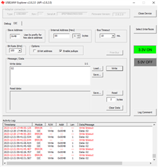
Other Parts Discussed in Thread: USB2ANY

Hi team,

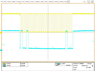
I use I2C communication to communicate MSP430FR2355 as slaver with PC as master.

Using the sample program in resource explorer for I2C communication, msp430fr235x_eusci_i2c_standard_slave.c, when I using USB2ANY to communicate PC with MSP430 to write and read data (P1.2/P1.3, Slave address 0x48). It always shows "write timeout". Pullup 4.7kohm resistors for SDA and SCL  are also added already.

Thanks for your help in advance.

  • HI Yibo,

    Do you have an oscilloscope or logic probe to capture the I2C signals?

  • Hi Dennis,

    As attached.

  • Thanks Yibo,

    Ok, looking at the waveforms, I see that the MSP has acknowledged or ACK'd (SDA low on 9th clock pulse) the USB2ANY.  This tells me the MSP430 is responding correctly to the data being sent from the USB ANY. 

    Not sure in this case why there is a timeout.  Let me dig up a USB2ANY and give it a try.

  • Thanks Dennis, by the way, after the address 0x48 and the register 0x00, the data according to the USB2ANY should be 0x02, but according to the waveform, it is 0x01? It also confuses me..

  • Hi Yibo,

    No, the waveform is correct.  See annotated diagram below. You can see the slave has /NACK (acknowledges) after each byte received.

  • Hi Dennis,

    USB2ANY: USB2ANY Interface Adapter - Amplifiers forum - Amplifiers - TI E2E support forums

    Through the above forum, I modified the program, which added some code(enable RX interrupt and read RXBUF data). And the write timeout problem seems to be fixed.

    The new question is.. when I read the data, the value is not what I wrote into the register.

    Following is my modified code and the result from USB2ANY,

    #include <msp430.h>
    #include <stdint.h>
    #include <stdlib.h>
    #include <driverlib.h>
    
    volatile unsigned char TXData;
    volatile unsigned char RXData;
    
    
    #define REGISTER_0_ADDRESS 0x00 // Replace with your chosen address
    #define REGISTER_1_ADDRESS 0x01 // Replace with another address
    
    // Define variables to store received values
    double A = 0.0;
    double B = 0.0;
    int i;
    
    uint8_t receivedbyte;
    
    
    int main(void)
    {
        WDTCTL = WDTPW | WDTHOLD;
    
        // Configure GPIO
        P1SEL0 |= BIT2 | BIT3;
        P1SEL1 &= ~(BIT2 | BIT3);
    
        // Disable the GPIO power-o9n default high-impedance mode to activate
        // previously configured port settings
        PM5CTL0 &= ~LOCKLPM5;
    
    
        // Configure USCI_B2 for I2C mode
        UCB0CTLW0 = UCSWRST;                    // Software reset enabled
        UCB0CTLW0 |= UCMODE_3 | UCSYNC;         // I2C mode, sync mode
        UCB0I2COA0 = 0x48 | UCOAEN;             // own address is 0x48 + enable
        UCB0CTLW0 &= ~UCSWRST;                  // clear reset register
        UCB0IE |= UCRXIE0 | UCTXIE0 | UCSTPIE;            // transmit,stop interrupt enable
    
        __bis_SR_register(LPM0_bits | GIE);     // Enter LPM0 w/ interrupts
        __no_operation();
    
        while (1) {
            PMM_unlockLPM5();
            // Toggle P1.0 output
    
            if(A==5){ //green
                P1OUT &= ~BIT0;                         // Clear P1.0 output latch for a defined power-on state
                P1DIR |= BIT0;                          // Set P1.0 to output direction
                P1OUT |= BIT0;
            }
            if(B==7){ //red
                P6OUT &= ~BIT6;                         // Clear P1.0 output latch for a defined power-on state
                P6DIR |= BIT6;                          // Set P1.0 to output direction
                P6OUT |= BIT6;
            }
            for(i=10000; i>0; i--);
            // Your application logic here
            // Process the received value (e.g., update LEDs, perform actions, etc.)
        }
    }
    
    #if defined(__TI_COMPILER_VERSION__) || defined(__IAR_SYSTEMS_ICC__)
    #pragma vector = EUSCI_B0_VECTOR
    __interrupt void USCI_B0_ISR(void)
    #elif defined(__GNUC__)
    void __attribute__ ((interrupt(EUSCI_B0_VECTOR))) USCI_B0_ISR (void)
    #else
    #error Compiler not supported!
    #endif
    {
        switch(__even_in_range(UCB0IV, USCI_I2C_UCBIT9IFG))
        {
            case USCI_NONE:          break;     // Vector 0: No interrupts
            case USCI_I2C_UCALIFG:   break;     // Vector 2: ALIFG
            case USCI_I2C_UCNACKIFG: break;     // Vector 4: NACKIFG
            case USCI_I2C_UCSTTIFG:  break;     // Vector 6: STTIFG
            case USCI_I2C_UCSTPIFG:             // Vector 8: STPIFG
                TXData = 0;
                UCB0IFG &= ~UCSTPIFG;           // Clear stop condition int flag
                break;
            case USCI_I2C_UCRXIFG3:  break;     // Vector 10: RXIFG3
            case USCI_I2C_UCTXIFG3:  break;     // Vector 12: TXIFG3
            case USCI_I2C_UCRXIFG2:  break;     // Vector 14: RXIFG2
            case USCI_I2C_UCTXIFG2:  break;     // Vector 16: TXIFG2
            case USCI_I2C_UCRXIFG1:  break;     // Vector 18: RXIFG1
            case USCI_I2C_UCTXIFG1:  break;     // Vector 20: TXIFG1
            case USCI_I2C_UCRXIFG0:
                RXData = UCB0RXBUF;
                if (RXData == REGISTER_0_ADDRESS) {
                    // Combine the received byte into A
                    uint64_t temp_A = *(uint64_t*)&A;
                    temp_A = (temp_A << 8) | receivedbyte;
                    A = *(double*)&temp_A;
    //                receiving_A = 0; // Switch to receiving B next
                }
                else if (RXData == REGISTER_1_ADDRESS) {
                                // Combine the received byte into B
                                uint64_t temp_B = *(uint64_t*)&B;
                                temp_B = (temp_B << 8) | receivedbyte;
                                B = *(double*)&temp_B;
                //                receiving_A = 1; // Switch back to receiving A
                }
                break;     // Vector 22: RXIFG0
            case USCI_I2C_UCTXIFG0:             // Vector 24: TXIFG0
                UCB0TXBUF = TXData++;
                break;
            case USCI_I2C_UCBCNTIFG: break;     // Vector 26: BCNTIFG
            case USCI_I2C_UCCLTOIFG: break;     // Vector 28: clock low timeout
            case USCI_I2C_UCBIT9IFG: break;     // Vector 30: 9th bit
            default: break;
        }
    }
    

    Thanks for your help in advance.

  • Hi Yibo,

    I apologize for the delay...do you still need help with your new question?

**Attention** This is a public forum