This thread has been locked.

If you have a related question, please click the "Ask a related question" button in the top right corner. The newly created question will be automatically linked to this question.

EVM430-FR6047: TIDA-01486: receiver amplifier response

Part Number: EVM430-FR6047
Other Parts Discussed in Thread: TINA-TI, TIDA-01486

Hi

I have bought the TIDA-01486 booster pcb and connected it to the EVM-FR6047. However I noticed that I had an ok echo over the transducer (1MHz frequency 80mV pk-2-pk, while I could only see a very weak echo when performing the adc capture with the USS design center program. After investigating I noticed some differences between the TINA-TI model provided for the TIDA-01486 and the schematic.

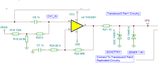
In the simulation model

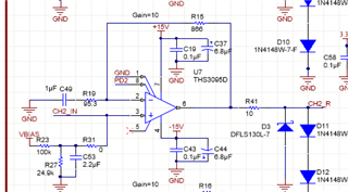
And the Altium schematic

Besides the different value for C7/C49 (which made the response better for my use), the C53 capacitor here seems to give negative gain when simulating, which also seemed to be in line with what I observed during testing.

However after removing the capacitor, I now seem to have stability problem as I see a lot of oscillations. I just wondered why the 2.2uF was added in the first place? Seems like the booster card cannot achieve 50db gain if I have done the simulation correctly.

  • Hi Hakon,

    I will reach out to the team that created this demo design to find the answer to this. Thank you in advance for your patience and please reply again to this thread to remind me if I do not update by the end of the week.

  • Hi Dylan,

    Thank you for your quick response. I did some simulations and ended up with replacing C54-C51 with a 2nF capacitor, and now the receiver is working as I expected (have not checked excactly how many db gain I have got but it is in the range of what I was expecting). Also only tested with a 1MHz transducer so far. Could there be an error in the altium schematics?

  • When you say working as expected, you mean achieving the correct gain? In your original post I think you said that the 2.2uF capacitor for C53 reflected the actual behavior of the physical board, is that correct?

    It is certainly possible that the wrong version of one of the documents is published online. I have reached out to a member of the team who released this design, but they are out of office until tomorrow. Once they return hopefully I will be able to pass on an explanation of what is going on here.

  • Ah sorry, I will explain.

    There are two differences between the TINA-TI and the schematic:

    1. The first difference is the value of C7 in the TINA-TI picture (labelled C49 in the altium schematic). The TINA-TI model has this as 1nF and altium schematic has it as 1uF. The difference in response is mostly where the -3db line happens, and a 1 uF cap here is what I would expect from the filter. Luckily I noticed the difference before I ordered the board, and since altium files have 1 uF and not 1nF, everything was fine. So most likely the TINA-TI model is wrong and C7 should be changed to 1uF. The TINA-TI model is the one that can be downloaded of TI-site for TIDA-01486.

    2. The 2.2uF capacitor labelled C53 in the altium schematic is not present in the simulation file. If I simulate with this cap present, the gain is not excactly great, and this is also what I experienced when testing the hardware and checking with oscilloscope. Removing the cap altogether made something unstable as I had large oscillations and high current consumption. I then simulated with a 2nF capacitor and ended up using this instead of 2.2 uF. Now the board is working as I expected.

    I am wondering if the 2.2uF should have been 2nF and that this is a bug in the altium schematics?

  • Also tried with a 560pF cap for C54-C51, this should give higher gain that 2nF (10 dB in pass-band for 2nF and approx. 17 db in passband for 560pF). Might test even lower to see If I can get close to 20dB

  • Thank you for the detailed answer. I see what you mean now. 

    Where did you download the Altium schematic? Looking at the TIDA-01486 page, at the Schematic - TIDA-01486 download link (TIDRWD6.PDF), C53 is marked at "Do Not Populate".  Are we looking at different schematic files?

    Have you checked the behavior of the device when you depopulate that capacitor?

  • Did not look to much at the PDF but used the altium files that are inside the TIDRWE0.ZIP --> https://www.ti.com/lit/zip/tidrwe0

    In the altium project there are two options for the C54-C51, not populated or 2.2uF. We ordered it with the 2.2uF but after realising how it changed the response I first removed it. Then I had large oscillations on the board. The oscillations disappeared after I inserting a smaller cap (2nF) for C54-C51, and the filter gain was acceptable. I have been testing a bit with 560pF also which gives higher gain and seems to work fine

  • Ah right sorry I got ahead of myself there. I've just pinged the engineer who created the design again to see what the explanation is for the discrepancy. I am glad to hear that you've been able to increase the gain to an acceptable level with your own changes.

  • Hi Hakon,

    I just heard back from our Systems engineer who worked on this design a while back. He said that he likely just changed it in his physical design when making the device, changed it in Altium, and not in the simulation.

    Bottom line is: It is good that you were able to test this and find a configuration that works well for your application. For all TI reference designs, we encourage customers to perform their own testing to find the optimal configuration for their end use. If you run into further issues with your design, please post a new thread so we can look into the issue further.

    I'll mark this post as resolved as we have no additional information on the matter, if you have continuing questions feel free to mark it not resolved and add more to the thread.

  • Hi Dylan,

    Thank you, I marked it as resolved now.

    Regards
    Håkon

**Attention** This is a public forum