This thread has been locked.

If you have a related question, please click the "Ask a related question" button in the top right corner. The newly created question will be automatically linked to this question.

MSP430F6779A: What happens if Vcore drop but there is no POR?

Part Number: MSP430F6779A

As with my present source code, the SVSLPE bits is clear.
(SVS low-side power-on reset is disabled)

PMMRIE      =   SVSHPE;

What happens if Vcore drop but there is no POR? (e.g. the MCU will stuck in reset state)

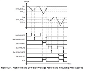
How to simulate Vcore drop but DVCC is kept (as Figure 2-4 in the user guide)?
  • Part Number: MSP430F6779A

    What is the purpose of disabling SVSHPE and SVSLPE?

    What happens if Vcore drop during this time without POR? (e.g. some severe events like MCU stuck may occur)

    uint16_t PMM_setVCoreUp ( uint8_t level){
        uint32_t PMMRIE_backup, SVSMHCTL_backup, SVSMLCTL_backup;
    
        //The code flow for increasing the Vcore has been altered to work around
        //the erratum FLASH37.
        //Please refer to the Errata sheet to know if a specific device is affected
        //DO NOT ALTER THIS FUNCTION
    
        //Open PMM registers for write access
        HWREG8(PMM_BASE + OFS_PMMCTL0_H) = 0xA5;
    
        //Disable dedicated Interrupts
        //Backup all registers
        PMMRIE_backup = HWREG16(PMM_BASE + OFS_PMMRIE);
        HWREG16(PMM_BASE + OFS_PMMRIE) &= ~(SVMHVLRPE | SVSHPE | SVMLVLRPE |
                                              SVSLPE | SVMHVLRIE | SVMHIE |
                                              SVSMHDLYIE | SVMLVLRIE | SVMLIE |
                                              SVSMLDLYIE
                                              );
        SVSMHCTL_backup = HWREG16(PMM_BASE + OFS_SVSMHCTL);
        SVSMLCTL_backup = HWREG16(PMM_BASE + OFS_SVSMLCTL);
    
        //Clear flags
        HWREG16(PMM_BASE + OFS_PMMIFG) = 0;
    
        //Set SVM highside to new level and check if a VCore increase is possible
        HWREG16(PMM_BASE + OFS_SVSMHCTL) = SVMHE | SVSHE | (SVSMHRRL0 * level);
    
        //Wait until SVM highside is settled
        while ((HWREG16(PMM_BASE + OFS_PMMIFG) & SVSMHDLYIFG) == 0) ;
    
        //Clear flag
        HWREG16(PMM_BASE + OFS_PMMIFG) &= ~SVSMHDLYIFG;
    
        //Check if a VCore increase is possible
        if ((HWREG16(PMM_BASE + OFS_PMMIFG) & SVMHIFG) == SVMHIFG){
            //-> Vcc is too low for a Vcore increase
            //recover the previous settings
            HWREG16(PMM_BASE + OFS_PMMIFG) &= ~SVSMHDLYIFG;
            HWREG16(PMM_BASE + OFS_SVSMHCTL) = SVSMHCTL_backup;
    
            //Wait until SVM highside is settled
            while ((HWREG16(PMM_BASE + OFS_PMMIFG) & SVSMHDLYIFG) == 0) ;
    
            //Clear all Flags
            HWREG16(PMM_BASE +
                OFS_PMMIFG) &= ~(SVMHVLRIFG | SVMHIFG | SVSMHDLYIFG |
                                 SVMLVLRIFG | SVMLIFG |
                                 SVSMLDLYIFG
                                 );
    
            //Restore PMM interrupt enable register
            HWREG16(PMM_BASE + OFS_PMMRIE) = PMMRIE_backup;
            //Lock PMM registers for write access
            HWREG8(PMM_BASE + OFS_PMMCTL0_H) = 0x00;
            //return: voltage not set
            return ( STATUS_FAIL) ;
        }
    
        //Set also SVS highside to new level
        //Vcc is high enough for a Vcore increase
        HWREG16(PMM_BASE + OFS_SVSMHCTL) |= (SVSHRVL0 * level);
    
        //Wait until SVM highside is settled
        while ((HWREG16(PMM_BASE + OFS_PMMIFG) & SVSMHDLYIFG) == 0) ;
    
        //Clear flag
        HWREG16(PMM_BASE + OFS_PMMIFG) &= ~SVSMHDLYIFG;
    
        //Set VCore to new level
        HWREG8(PMM_BASE + OFS_PMMCTL0_L) = PMMCOREV0 * level;
    
        //Set SVM, SVS low side to new level
        HWREG16(PMM_BASE + OFS_SVSMLCTL) = SVMLE | (SVSMLRRL0 * level) |
                                             SVSLE | (SVSLRVL0 * level);
    
        //Wait until SVM, SVS low side is settled
        while ((HWREG16(PMM_BASE + OFS_PMMIFG) & SVSMLDLYIFG) == 0) ;
    
        //Clear flag
        HWREG16(PMM_BASE + OFS_PMMIFG) &= ~SVSMLDLYIFG;
        //SVS, SVM core and high side are now set to protect for the new core level
    
        //Restore Low side settings
        //Clear all other bits _except_ level settings
        HWREG16(PMM_BASE + OFS_SVSMLCTL) &= (SVSLRVL0 + SVSLRVL1 + SVSMLRRL0 +
                                               SVSMLRRL1 + SVSMLRRL2
                                               );
    
        //Clear level settings in the backup register,keep all other bits
        SVSMLCTL_backup &=
            ~(SVSLRVL0 + SVSLRVL1 + SVSMLRRL0 + SVSMLRRL1 + SVSMLRRL2);
    
        //Restore low-side SVS monitor settings
        HWREG16(PMM_BASE + OFS_SVSMLCTL) |= SVSMLCTL_backup;
    
        //Restore High side settings
        //Clear all other bits except level settings
        HWREG16(PMM_BASE + OFS_SVSMHCTL) &= (SVSHRVL0 + SVSHRVL1 +
                                               SVSMHRRL0 + SVSMHRRL1 +
                                               SVSMHRRL2
                                               );
    
        //Clear level settings in the backup register,keep all other bits
        SVSMHCTL_backup &=
            ~(SVSHRVL0 + SVSHRVL1 + SVSMHRRL0 + SVSMHRRL1 + SVSMHRRL2);
    
        //Restore backup
        HWREG16(PMM_BASE + OFS_SVSMHCTL) |= SVSMHCTL_backup;
    
        //Wait until high side, low side settled
        while (((HWREG16(PMM_BASE + OFS_PMMIFG) & SVSMLDLYIFG) == 0) ||
               ((HWREG16(PMM_BASE + OFS_PMMIFG) & SVSMHDLYIFG) == 0)) ;
    
        //Clear all Flags
        HWREG16(PMM_BASE + OFS_PMMIFG) &= ~(SVMHVLRIFG | SVMHIFG | SVSMHDLYIFG |
                                              SVMLVLRIFG | SVMLIFG | SVSMLDLYIFG
                                              );
    
        //Restore PMM interrupt enable register
        HWREG16(PMM_BASE + OFS_PMMRIE) = PMMRIE_backup;
    
        //Lock PMM registers for write access
        HWREG8(PMM_BASE + OFS_PMMCTL0_H) = 0x00;
    
        return ( STATUS_SUCCESS) ;
    }

  • Could you explain more detail (said in the user guide 2.2.2 Supply Voltage Supervisor and Monitor)

    about disruptive conditions at external VCORE pin and parasitic events at the external VCORE pin?

  • Hi Tink,

    The SVSHPE  and SVSLPE are disabled to prevent an accidental POR operation during the VCORE setup. You would still get a POR if your VDD drops below the required levels for operation.

    The disruptive conditions to VCORE could be parasitics with traces too close to the VCORE pin/ VCORE capacitor. Other signals that could couple onto VCORE due to PCB design could cause fluctuations on the VCORE and drop the voltage below the expected value. Generally, the parasitics are a non-issue if you keep the other signal traces away from VCORE; the VCORE pin is a corner pin so it would be easier to keep the VCORE away from other signals.

    I have noticed a couple of posts you're having involving the operation of VCORE level increase and a possibility of an MCU stuck event.

    1. Have you scoped the VCORE capacitor during operation to see the values when the MCU gets stuck?
    2. How are you identifying the MCU isn't progressing in code?
      1. Does it stop at a consistent line in the code?
    3. Are you able to easily replicate the issue you have been running into to run additional tests or is it seemingly random?

    Regards,
    Luke

  • 1) Have you scoped the VCORE capacitor during operation to see the values when the MCU gets stuck?
    Yes, I have measured the VCORE when the MCU gets stuck, the (VCORE) = 1.42 V

    2) How are you identifying the MCU isn't progressing in code?
    Checking by evidence below
    1) Reset pin get high: if the code process the reset pin is shall be low with NMI function.
    2) The Vcore: if the code process the Vcore shall be change to 2, 3, 0 LPM with ours features

    but this time stuck only the vcore 0 (1.42 V)

    Does it stop at a consistent line in the code?
    I found only if the code stop at system pre-init function but cannot make it stop here in the lab.

    int system_pre_init(void)
    {
    
        WDTCTL = WDTPW+WDTHOLD;
    
        // Clear RTCHOLD Bit after reset
        RTCCTL0_H = RTCKEY_H;     // unlock
        RTCCTL1 &= ~RTCHOLD;      // release RTC
        RTCCTL0_H = 0x00;         // lock
    
        SFRRPCR = SYSNMI | SYSNMIIES | SYSRSTRE;
    
        return 1;
    }


    3) Are you able to easily replicate the issue you have been running into to run additional tests or is it seemingly random?
    I cannot reproduce this problem in the lab, only found in actual using field.

  • Hi Tink,

    The VCORE value seems correct for Core0 in active mode.

    Additionally on 2, are you able to connect to the device and step through the code? I want to verify that the MCU won't continue with operation in the code. If it does continue then the debugger may be assisting so we can't rule out what happens in Run Mode.

    Do you see this on multiple devices?

    Have you checked the PMM erratas to verify that you are not running any of those scenarios in your process flow?

    Regards,
    Luke

  • Hi Luke,

    Additionally on 2, are you able to connect to the device and step through the code?

    No, I did not use debugger checking the actual sample "the MCU gets stuck". Because I worry about it will reset the MCU or Program Counter (so, the problem and cause evidence may disappear).

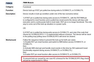
    So, I have reproduce with the PMM26 conditions with another board(modified source code) to make "the MCU get stuck".

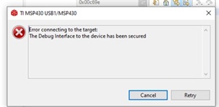
    After that try to use debugger,  It cannot connect to the MCU using CCS.

    Do you see this on multiple devices?

    Yes, the problem occurs in multiple devices in actual field (I estimated 0.5 to 1 %).

    Have you checked the PMM erratas to verify that you are not running any of those scenarios in your process flow?

    Yes, I have checked the errata. the source code mostly do as the prevention workaround process.

    except some point i found below.

    "To prevent lock-up caused by use case #2 a timeout for the SVSMLDLYIFG flag check
    should be implemented to 300us."

    But I don't think the above causes the problem because in the source code there is no pull check. SVSMLDLYIFG==1.

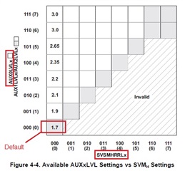
  • Another point i suspect, why the default value of AUX0LVL and SVSMHRRL reside in in invalid area (AUX0LVL = 0, SVSMHRR = 0) in the user guide.

    Is this possibly cause MCU running the stuck in reset as i found?

    multiple
  • I don't see the code snippets in this thread setting the RST pin to be an NMI interrupt instead of the RST function. Do you see this being a possible situation in the field. Where your device is setting the SVS module and a rst is occurring? May be best to add before the PMM set VCORE function to change the RST pin to an NMI.

    In the NMI you can still handle the interrupt how you see fit (whether to actually reset the code or just continue with the vcore setup).

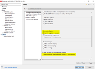
    For the CCS connection, in your project properties you can set the debugger to do a 'halt on connect' instead of resetting on connect. You can also load in the symbols from the code so CCS and the debugger can connect and step through without having to reset or program the device.

    ---

    For the AUX0LVL question. This is only for when the switching is enabled, which by default it is disabled.

    I recommend to increase the level of AUX0LVL when you enable the switching.

    Regards,
    Luke

  • Hi ,

    about increase the level of AUX0LVL when you enable the switching.

    Do you think code below correct? It is about setting the level and then unlock the supply to be switching.

    Is process correct if in the first line change to AUXKEY?(to unlock at the same time).

        AUXCTL0_H = AUXKEY_H;
        AUXIE     = 0x0000;                         // AUXIE
        AUXCTL2   =  (AUXMR_0 | AUX0LVL_6 | AUX1LVL_3 | AUX2LVL_0);
        AUXIFG   &= ~(AUX0SWIFG | AUX1SWIFG | AUX2SWIFG | AUX0DRPIFG | AUX1DRPIFG | AUX2DRPIFG | AUXMONIFG | AUXSWNMIFG);
    
        AUXCTL1 |=   AUX2MD;                        // AUXCTL1    Software controlled AUXVCC2 auxiliary supply mode.
        AUXCTL1 &= ~(AUX0MD | AUX1MD);              //            Hardware controlled AUXVCC1 auxiliary supply mode.
                                                    //            Hardware controlled AUXVCC0 auxiliary supply mode.
        AUXIFG   &= ~(AUX0SWIFG | AUX1SWIFG | AUX2SWIFG | AUX0DRPIFG | AUX1DRPIFG | AUX2DRPIFG | AUXMONIFG | AUXSWNMIFG);
                                                    // AUXIFG
        if ((AUXCTL0_L & LOCKAUX_L) == LOCKAUX_L)   // Auxiliary is locked because of core power down?
        {
            AUXCTL0_L &= ~LOCKAUX_L;                // Release Auxiliary module from core power down
        }

  • Hi Tink,

    You will need to verify that the Auxiliary Module isn't locked first and write the key. On line 1, if you change it from

    AUXCTL0_H = AUXKEY_H;

    to

    AUXCTL0 = AUXKEY_H;

    Then I believe you will unlock the auxiliary module and allow it to be written too. Otherwise I don't think the auxiliary module is getting written to off a reset/power on.

    Regards,

    Luke

  • Hi Luke,

    let back to preset my source code.

    Step 1: before line 1 AUXCTL0_H = AUXKEY_H;

    Step 2: after line 1 AUXCTL0_H = AUXKEY_H;

    Step 3: after line 3 AUXCTL2   =  (AUXMR_0 | AUX0LVL_6 | AUX1LVL_3 | AUX2LVL_0);

    Step 4: after line 13  AUXCTL0_L &= ~LOCKAUX_L;

    Why this code can write the setting in step3 without "writing AUXKEY and LOCKAUX bit is clear" (step 1 only write key)?

    Does it conflict with the user guide?

  • Hi Tink,

    That does conflict with the user's guide. Let me see if I can recreate this on my end.

    Regards,

    Luke

  • Hi,

    Are there any updates?

  • Hi Tink,

    I have tested on my side and I'm still looking into this.

    Regards,

    Luke

  • Hi, any update?

**Attention** This is a public forum