This thread has been locked.

If you have a related question, please click the "Ask a related question" button in the top right corner. The newly created question will be automatically linked to this question.

MSP430G2553: How to Enter BSL

Part Number: MSP430G2553

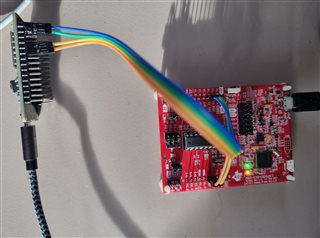
Hello, sorry for the stupid question but somehow I stuck in the mud. I like to enter BSL on a simple launchpad (final app will use FR6047 but for simplicity I take the launchpad) from an ESP32s Serial (first image). I connect RX/TX, RST, TEST and write super simple sketch:

#include <HardwareSerial.h>

#define PIN_RST 19
#define PIN_TEST 21
#define PIN_TX2 22
#define PIN_RX2 23

HardwareSerial MySerial1(1);

void setup() {
Serial.begin(115200);
MySerial1.begin(9600, SERIAL_8E1, PIN_RX2, PIN_TX2);

pinMode(PIN_TEST,OUTPUT);
pinMode(PIN_RST,OUTPUT);
digitalWrite(PIN_TEST,LOW);
digitalWrite(PIN_RST,LOW);
delay(20);
digitalWrite(PIN_TEST,HIGH);
delay(20);
digitalWrite(PIN_TEST,LOW);
delay(20);
digitalWrite(PIN_TEST,HIGH);
delay(20);
digitalWrite(PIN_RST,HIGH);
delay(20);
digitalWrite(PIN_TEST,LOW);
delay(200);
}

void loop() {
MySerial1.print(0x80);
delay(100);
if (MySerial1.available() > 0) {
int c = MySerial1.read();
Serial.printf("Rec: 0x%02x (%d) \n",c,c);
}
delay(1000);
}

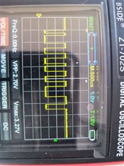
I can see that the main apps stops when executing the BSL pin sequence. Now I send the 0x08 and I can even see this on the  >> RDX line (see image). On the TXD line there is no signal back, constant 3.3V. 
Am I using the wrong pin for TXD? As second hardware I use the EVM430FR6047 board where I assume the four pints are all on J3

Greetings Christian

  • From the datasheet, BSL TX/RX pins are defined as in the below image.

  • Thank you for this. According to slau550ab.pdf the cheap G2553 does not even have UART BSL. Hence I switched over to EVM-FR6047 following same command. I use the BSL-Scripter precompiled for testing on USCLA0 and indeed I can see some reaction on the pins on 9600 Baud when executing
    LOG
    MODE FRxx UART 9600 /dev/tty.usbserial-120
    RX_PASSWORD pass32_default.txt
    RX_DATA_BLOCK blinkLED_FR6989.txt

    on the scripter.  I don't use the Rocket but a simple USB UART and turn the BSL on with App software command not to deal with the TEST pins etc.
    This proofs that BSL is active and the pins are correct. However, I don't get  what I would expect according to SLAU655G– (BSL Scripter Manual) )but
    MODE FRxx UART 9600 /dev/tty.usbserial-120
    RX_PASSWORD pass32_default.txt
    Read Txt File : /Users/christian/ti/BSL-Scripter/pass32_default.txt
    [ACK_ERROR_MESSAGE]Packet Size exceeds maximum buffer size!
    RX_DATA_BLOCK blinkLED_FR6989.txt
    Read Txt File : /Users/christian/ti/BSL-Scripter/blinkLED_FR6989.txt
    [ACK_ERROR_MESSAGE]Header incorrect!
    [ACK_ERROR_MESSAGE]Header incorrect!
    [ACK_ERROR_MESSAGE]Packet Size exceeds maximum buffer size!
    Time elapsed of writing 262 bytes : 0.05788 seconds
    Speed of writing data :4.42(kB/s)
    CRC_CHECK 0x4400 0x0020
    [ACK_ERROR_MESSAGE]Header incorrect!
    SET_PC 0x4400

    The error message swtches between "Header incorrect" and "Packet Size exceeds maximum buffer size". When I use a plain UART terminal with binary support I can send e.g.0x80 but then I receive 0x51 as answer - still not what the slau550ab.pdf would describe.

    First general question. Is the approach correct? Will BSL Scripter even work with FR6047? Can I use a standard USB UART with Parity and one stop bit?  

  • Not sure where you see that the G2553 does not have a UART BSL as it shows in the G2xx3 column of table 2-1 the UART BSL is provided. As another aside, remember that the FR6047 and the G2553 have different BSL communication protocols. For the G2553, you should be referencing SLAU319, MSP430 Flash Devices Bootloader. For the FR6047, you should be referencing SLAU550 which is specific to FRAM-based devices.

    I have never used the BSL scripter, and only use a USB to UART converter with 9600 baud and even parity. Not sure if the BSL scripter even supports anything other than TI tools since it assumes it needs to manipulate the TST and RST pins to invoke the bootloader. If you plan to program fresh (unprogrammed) devices with the BSL in the future, it would be required to implement the TST and RST pin toggling.

    That said, I don't think you are actually setting even parity. According to the scripter documentation, the MODE command defaults to NO parity. With my FR6043 and a USB-UART bridge set to 9600 baud and EVEN parity, if I send a byte other than 0x80, I get a 0x51 as a response. According to the FRAM Devices BSL user guide (SLAU550) Table 4-6, that means "Header incorrect. The packet did not begin with the required value of 0x80". If you send 0x80 correctly, you will not receive a response until a complete packet is sent.

  • Works now. was UART problem not related to the MSP430. Thanks for the support - pointed me into the right direction

**Attention** This is a public forum