This thread has been locked.

If you have a related question, please click the "Ask a related question" button in the top right corner. The newly created question will be automatically linked to this question.

LP-MSPM0G3507: TRIM Settings affecting PLL

Part Number: LP-MSPM0G3507
Other Parts Discussed in Thread: MSPM0G3507

Hi Team,

Working with MSPM0G3507 (Launchpad) we are trying to apply a TRIM on SYSOSC at 16Mhz and then apply a PLL to reach 80Mhz.

But facing some issues, sometimes the SYOSC gets back to 32Mhz when applying the PLL, and at other times the CPUCLK isn’t 80Mhz.

Without TRIM, a PLL can be applied with no problem.

Can you suggest us any next steps?

Best Regards,

Madhurya 

  • Hi Madhurya,

    When are they seeing the 32MHz? is this after a part reset before they set the SYSOSC to utilize the user trim configuration?

    What clock rate are they seeing when they set the CPU CLK to 80MHz?

    Regards,

    Luke

  • I did the calibration following slau846a 2.3.1.2.4 aiming 16Mhz on SYSOSC, with PLL disabled. When I was applying TRIM values, I didn't need to reset the MCU, resetting or not I was measuring the same value. I did the calibration following the config as Test 1.

    Test 1:

    Using ENABLE_USE_PLL = 0, FCL_ENABLED = 1, FCL_BEFORE = 1, measuring 16.05Mhz, even after reset the MCU.


    Test 2:

    Using ENABLE_USE_PLL = 0, FCL_ENABLED = 1, FCL_BEFORE = 0, measuring 32Mhz before reset, after reset the MCU 15.0Mhz.

    Test 3:

    Using ENABLE_USE_PLL = 1, FCL_ENABLED = 1, FCL_BEFORE = 1, when I apply I'm measuring 32.4Mhz, even after reset the MCU. This is following the recommendations on slau846a SYSPLL Usage Example (pag. 114) and Trim procedure using CLK_OUT with frequency correction loop (FCL) enabled (ROSC resistor present) (pag. 111). This is what I consider be the right way to apply the TRIM and the PLL, but the result was not the expected.


    Test 4:

    By using ENABLE_USE_PLL = 1, FCL_ENABLED = 1, FCL_BEFORE = 0, when I apply I'm measuring 32.4Mhz, but after reset the MCU change to 15.0Mhz the same as Test 2


    Follow my test code:

    /*
     * Copyright (c) 2023, Texas Instruments Incorporated
     * All rights reserved.
     *
     * Redistribution and use in source and binary forms, with or without
     * modification, are permitted provided that the following conditions
     * are met:
     *
     * *  Redistributions of source code must retain the above copyright
     *    notice, this list of conditions and the following disclaimer.
     *
     * *  Redistributions in binary form must reproduce the above copyright
     *    notice, this list of conditions and the following disclaimer in the
     *    documentation and/or other materials provided with the distribution.
     *
     * *  Neither the name of Texas Instruments Incorporated nor the names of
     *    its contributors may be used to endorse or promote products derived
     *    from this software without specific prior written permission.
     *
     * THIS SOFTWARE IS PROVIDED BY THE COPYRIGHT HOLDERS AND CONTRIBUTORS "AS IS"
     * AND ANY EXPRESS OR IMPLIED WARRANTIES, INCLUDING, BUT NOT LIMITED TO,
     * THE IMPLIED WARRANTIES OF MERCHANTABILITY AND FITNESS FOR A PARTICULAR
     * PURPOSE ARE DISCLAIMED. IN NO EVENT SHALL THE COPYRIGHT OWNER OR
     * CONTRIBUTORS BE LIABLE FOR ANY DIRECT, INDIRECT, INCIDENTAL, SPECIAL,
     * EXEMPLARY, OR CONSEQUENTIAL DAMAGES (INCLUDING, BUT NOT LIMITED TO,
     * PROCUREMENT OF SUBSTITUTE GOODS OR SERVICES; LOSS OF USE, DATA, OR PROFITS;
     * OR BUSINESS INTERRUPTION) HOWEVER CAUSED AND ON ANY THEORY OF LIABILITY,
     * WHETHER IN CONTRACT, STRICT LIABILITY, OR TORT (INCLUDING NEGLIGENCE OR
     * OTHERWISE) ARISING IN ANY WAY OUT OF THE USE OF THIS SOFTWARE,
     * EVEN IF ADVISED OF THE POSSIBILITY OF SUCH DAMAGE.
     */
    
    #include "ti_msp_dl_config.h"
    
    volatile uint32_t mSysCTL = 0x0000000;
    
    #define POWER_STARTUP_DELAY                                                (16)
    
    
    #define GPIO_CLKOUT_PORT                                                   GPIOA
    #define GPIO_CLKOUT_PIN                                           DL_GPIO_PIN_14
    #define GPIO_CLKOUT_IOMUX                                        (IOMUX_PINCM36)
    #define GPIO_CLKOUT_IOMUX_FUNC                   IOMUX_PINCM36_PF_SYSCTL_CLK_OUT
    #define GPIO_ROSC_PORT                                                     GPIOA
    #define GPIO_ROSC_PIN                                              DL_GPIO_PIN_2
    #define GPIO_ROSC_IOMUX                                           (IOMUX_PINCM7)
    #define CPUCLK_FREQ                                                     32000000
    
    #define ENABLE_USE_PLL                                                  1 // 0 - DISABLE / 1 - ENABLE
    #define FCL_ENABLED                                                     1 // 0 - DISABLE / 1 - ENABLE
    #define FCL_BEFORE                                                      1 // 0 - AFTER / 1 - BEFORE
    
    void mySysInit()
    {
        DL_GPIO_reset(GPIOA);
        DL_GPIO_reset(GPIOB);
    
        DL_GPIO_enablePower(GPIOA);
        DL_GPIO_enablePower(GPIOB);
        delay_cycles(POWER_STARTUP_DELAY);
    
    
        DL_GPIO_initPeripheralOutputFunction(GPIO_CLKOUT_IOMUX, GPIO_CLKOUT_IOMUX_FUNC);
        DL_GPIO_enableOutput(GPIO_CLKOUT_PORT, GPIO_CLKOUT_PIN);
        DL_GPIO_initPeripheralAnalogFunction(GPIO_ROSC_IOMUX);


        DL_SYSCTL_setSYSOSCFreq(DL_SYSCTL_SYSOSC_FREQ_BASE);
        /* Set default configuration */
        DL_SYSCTL_disableHFXT();
        DL_SYSCTL_disableSYSPLL();
        //DL_SYSCTL_enableExternalClock(DL_SYSCTL_CLK_OUT_SOURCE_SYSPLLOUT1,
        //    DL_SYSCTL_CLK_OUT_DIVIDE_2);
        DL_SYSCTL_enableExternalClock(DL_SYSCTL_CLK_OUT_SOURCE_SYSOSC,
                DL_SYSCTL_CLK_OUT_DIVIDE_DISABLE);
    
        //Low Power Mode is configured to be SLEEP0
        DL_SYSCTL_setBORThreshold(DL_SYSCTL_BOR_THRESHOLD_LEVEL_0);
    }
    
    int main(void)
    {
        //SYSCFG_DL_init();
        mySysInit();
    
    #if (FCL_ENABLED == 1 && FCL_BEFORE == 1)
        // Need to be at FREQ_BASE
        DL_SYSCTL_enableSYSOSCFCL();   
    #endif
    
        /**
         * FCL Disabled
         *      RDIV    0x150 
         *      FINE    0x08
         *      COARSE  0x13
         *      CAP     0x01
         * 
         * FCL Enabled
         *      RDIV    0x150 
         *      FINE    0x08
         *      COARSE  0x13
         *      CAP     0x01
        */
    
        DL_SYSCTL_SYSOSCUserTrimConfig myTrim =
            {
                 0x150,                             // RDIV
                 0x08,                              // resistorFine
                 0x15,                              // resistorCoarse
                 0x01,                              // capacitor
                 DL_SYSCTL_SYSOSC_USERTRIM_FREQ_16M
            };       //Trim Config
    
        DL_SYSCTL_configSYSOSCUserTrim(&myTrim);                                                                        //Writing the SYSOSC User Register
    
        DL_SYSCTL_setSYSOSCFreq(DL_SYSCTL_SYSOSC_FREQ_USERTRIM);                                                        //Updating the SYSOSC Frequency to User Value
        /*WOTHOUT ROSC END*/
    
    #if (FCL_ENABLED == 1 && FCL_BEFORE == 0) 
        /*WITH ROSC START*/
        DL_SYSCTL_setSYSOSCFreq(DL_SYSCTL_SYSOSC_FREQ_BASE);                                                            // changing the SYSOSC to Base i.e. 32MHz
        DL_SYSCTL_enableSYSOSCFCL();                                                                                    // Enabling the FCL
        DL_SYSCTL_setSYSOSCFreq(DL_SYSCTL_SYSOSC_FREQ_USERTRIM);                                                        // Changing to trim value frequency
    #endif
    
    #if (ENABLE_USE_PLL == 1)
    
        static const DL_SYSCTL_SYSPLLConfig gSYSPLLConfig = {
            .inputFreq              = DL_SYSCTL_SYSPLL_INPUT_FREQ_16_32_MHZ,
            .rDivClk2x              = 3,
            .rDivClk1               = 1,
            .rDivClk0               = 0,
            .enableCLK2x            = DL_SYSCTL_SYSPLL_CLK2X_ENABLE,
            .enableCLK1             = DL_SYSCTL_SYSPLL_CLK1_ENABLE,
            .enableCLK0             = DL_SYSCTL_SYSPLL_CLK0_DISABLE,
            .sysPLLMCLK             = DL_SYSCTL_SYSPLL_MCLK_CLK2X,
            .sysPLLRef              = DL_SYSCTL_SYSPLL_REF_SYSOSC,
            .qDiv                   = 9,
            .pDiv                   = DL_SYSCTL_SYSPLL_PDIV_2,
    
        };
        DL_SYSCTL_setSYSOSCFreq(DL_SYSCTL_SYSOSC_FREQ_BASE);
        DL_SYSCTL_configSYSPLL((DL_SYSCTL_SYSPLLConfig *) &gSYSPLLConfig);
        DL_SYSCTL_setULPCLKDivider(DL_SYSCTL_ULPCLK_DIV_2);
    
        while((DL_SYSCTL_getClockStatus() & DL_SYSCTL_CLK_STATUS_SYSPLL_GOOD) != DL_SYSCTL_CLK_STATUS_SYSPLL_GOOD);
        
        DL_SYSCTL_setMCLKSource(SYSOSC, HSCLK, DL_SYSCTL_HSCLK_SOURCE_SYSPLL);
        DL_SYSCTL_setMCLKDivider(DL_SYSCTL_MCLK_DIVIDER_DISABLE);
    
    
        DL_SYSCTL_setSYSOSCFreq(DL_SYSCTL_SYSOSC_FREQ_USERTRIM);
    #endif
    
        while (1) {
            mSysCTL = SYSCTL->SOCLOCK.SYSOSCFCLCTL;
        }
    }


    Questions:
    1- I'm assuming the Test 3 is the right way to apply the TRIM and PLL, but when we measure the SYSOSC the value isn't expected. Are we doing the wrong process?

    2- Since we'll use PLL in different values but mainly at 80Mhz, should we perform the calibration with PLL enabled looking on the final value, or PLL disabled but looking on SYSOSC USER value, like 16Mhz? Because we are planning to use different clock frequencies with PLL, at least two (80Mhz and another lower to fit our current consumption in low power mode)

    3- Do we need to perform the reset to check the clock every time we change the TRIM values? We're thinking to make a function to calibrate automatic, but a reset on each change will be harder to the process.

    4- To apply PLL the reference manual said we need to change to FREQ BASE before apply PLL, but since we're planning to use 16Mhz FREQ USER the PLL parameters are different. So if we'll use 80Mhz using PLL from 16Mhz, when we apply the PLL we use the values looking directly to the final value, or should we apply some logic value thinking on 32Mhz and then after apply FREQ USER we change the PLL value? This is a bit fuzzy on the reference manual.

  • Hi Ulysses,

    Can you add a divider on your clock out signal?

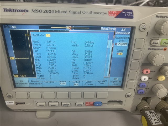
    1. I'm suspicious of your clock signal because the edges of your clock signal are not defined. They ramp as if there is a capacitor on the signal.
    2. I would set your target based on the Sysosc accuracy, the SYSPLL is largely dependent on your input accuracy.
    3. You should not need to reset the device every time you change the TRIM values.
      1. You will need to return to the base frequency then update the trim values, then return back to the User Trim frequency.
      2. If you have a low-frequency crystal you could use the Frequency counter to help automate the updates to your User Trim. I haven't tested the idea personally but the theory is there. I can expand more on this idea if you're interested.
    4. Let me check why this limitation is listed in the User's Guide.

    Regards,
    Luke

  • Hi Luke,

    Yes, I'll rerun my tests with divider 2.

    1. Agree with you, this was the signal I did see on all my tests, but I don't have anything connected, is the pin (A14) directly to oscilloscope. I'm using the Launchpad mspm0g3507, clock output on A14 pin. I'm using a oscilloscope 100Mhz 1GSa/s.
    2. Ok, is what I expect, just checking 
    3. a. good to know
        b. I'm interested on this. Probably we'll use this 

    4. Let me know more about this, because this is a bit confused to me

  • Hi Ulysses,

    Just wanted to provide a follow-up that I am still looking into the notes that are in the TRM, and to get clarification if you could run the SYSOSC at user trim values instead of the 'base frequency'.

    Regards,

    Luke

  • Hi Luke,

    Do you have updates about this ticket?

  • Hi Ulysses,

    The sysosc needs to be at the base frequency for the internal system to execute the PLL properly. As you can put an external crystal through the PLL at 16-48 MHz this limitation isn't from the PLL.

    The note in the TRM is correct.

    Regards,
    Luke

  • Hi Luke,

    Ok, but my question is, once I'm using the SYSOSC at User frequency (16Mhz), and need my CPUCLK at 80Mhz, how is the correct way to apply the PLL? 

    1- SYSOSC = BASE_FREQ
    2- apply PLL parameters thinking on USER_FREQ (16Mhz) to get 80Mhz
    3- change SYSOSC to USER_FREQ

    This is the correct way?

  • Hi Ulysses,

    When using sysosc as the source for the syspll the sysosc needs to be at base frequency. I had attempted to manually change it but the sysosc will stay at 32MHz when using SYSPLL.

    Regards,
    Luke

  • Hi Luke,

    Ok, so if I understand correctly we aren't able to run the PLL with sysosc at user frequency, is correct? If my understand is correct, how can we improve the clock precision, once we'll need PLL? Today we can see an error around 2% on sysosc at base frequency, and this isn't acceptable on our system, we need something around 0.5%.

  • Hi Ulysses,

    With the ROSC resistor you should be getting much better accuracy than 2%. The left graph is the sysosc accuracy with FCL and the rosc resistor. The typical value is within 0.5% and the range of your end applications operating temperature will change the expected values.

    Regards,
    Luke

  • Hi Ulysses,

    I created a timer example that will get a higher accuracy timer based on the actual frequency of the SYSPLL.

    Let me know if you have any follow up questions.

    timer_higher_accuracy_example.zip

    Regards,
    Luke

**Attention** This is a public forum