Hello!
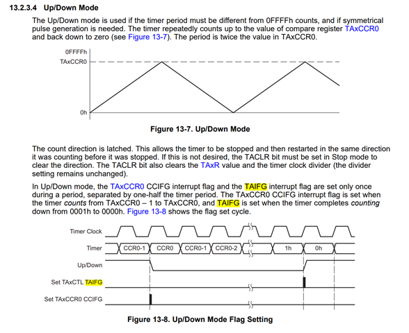
I am working with a MSP430FR2476 in LPM3.5 and waking up with RTC. Once the micro is up from LPM3.5 I to use Timer A0 in UP-DOWN mode to have a timeout inside a function so that I can get out in case I take too long, but I am not getting inside the TIMER0_A1_ISR.
I haven't seen any examples where a timer is used as a timer (not for waking up from LPM3.5) alongside RTC for waking up from LPM3.5.
I wanted to know if i am missing some configuration on the RTC side or the LPM3.5 side.
When I was using LPM4 and a port interruption to wake up from LPM4 mode the timer A timeout was working fine.
I am using the driver libraries RTC.h and timer_a.h from the SDK from MSP430FR2476
This is my RTC initialization:
void initRTC(bool irqEnable,bool minsOrSec, uint16_t t)
{
    WDTCTL = WDTPW | WDTHOLD;               // Stop watchdog timer
    uint16_t modulo;

    uint32_t mod;
    if(minsOrSec)
    {
       mod = t * 32 * 60; // Dado que al hacer 32 * t_tick = 1s * 60 = 1m
    }
    else
    {
        mod = t * 32;
    }

    //Testing
    //modulo = 32; //-->IRQs cada 1seg

    modulo = 57600; // --> IRQs cada 30mins
    if(mod < modulo)
    {
        modulo = (uint16_t)mod;
    }
    else
    {
        cantIRQs = (uint16_t)(mod/modulo); // A priori nos va a dar un numero entero. (seconds = 21600 --> 6h)
    }

    *(unsigned int*)(BKMEM_BASE) = (unsigned int)cantIRQs;
    *(unsigned int*)(BKMEM_BASE+2) = (unsigned int)countIRQs;
    P2SEL0 |= BIT0 | BIT1;                  // set XT1 pin as second function

    do
    {
        CSCTL7 &= ~(XT1OFFG | DCOFFG);      // Clear XT1 and DCO fault flag
        SFRIFG1 &= ~OFIFG;
    } while (SFRIFG1 & OFIFG);              // Test oscillator fault flag

    // Initialize RTC
    // Source = 32kHz crystal, divided by 1024
    RTC_clearInterrupt(RTC_BASE,RTC_OVERFLOW_INTERRUPT_FLAG);

    __bis_SR_register(GIE); //Enable interrupts

    RTC_init(RTC_BASE, modulo - 1, RTC_CLOCKPREDIVIDER_1024);
    RTC_enableInterrupt(RTC_BASE, RTC_OVERFLOW_INTERRUPT);
    RTC_clearInterrupt(RTC_BASE,RTC_OVERFLOW_INTERRUPT_FLAG);
    RTC_start(RTC_BASE,RTC_CLOCKSOURCE_XT1CLK);//RTC_CLOCKSOURCE_XT1VLOCLK

 }
This is how I enter LPM3.5 mode
    PMMCTL0_H = PMMPW_H;                    // Open PMM Registers for write
    PMMCTL0_L |= PMMREGOFF;                 // and set PMMREGOFF

    __bis_SR_register(LPM3_bits | GIE);     // Enter LPM3.5 and Enable Interruptions
This is how i init the timer A instance 0
    //Initialize Timer0_A3 --> Up-Down Mode
    Timer_A_initUpDownModeParam upDownCtr;
    upDownCtr.clockSource = TIMER_A_CLOCKSOURCE_ACLK;
    upDownCtr.clockSourceDivider = TIMER_A_CLOCKSOURCE_DIVIDER_1;
    upDownCtr.timerPeriod = 65535;  //From 0h to 0FFFFh  --> ~ 4 seg (updown)
    upDownCtr.timerInterruptEnable_TAIE = TIMER_A_TAIE_INTERRUPT_ENABLE;
    upDownCtr.captureCompareInterruptEnable_CCR0_CCIE = TIMER_A_CCIE_CCR0_INTERRUPT_DISABLE;
    upDownCtr.timerClear = TIMER_A_DO_CLEAR;
    upDownCtr.startTimer = false;

    Timer_A_initUpDownMode(TIMER_A0_BASE ,&upDownCtr);
When waking up from RTC I run the initialization of everything i needed again and then I start the timer A with Timer_A_startCounter(TIMER_A0_BASE,TIMER_A_UPDOWN_MODE); but I never reached the timer interruption:
// Timer0_A3 CC1-2, TA Interrupt Handler
#if defined(__TI_COMPILER_VERSION__) || defined(__IAR_SYSTEMS_ICC__)
#pragma vector = TIMER0_A1_VECTOR
__interrupt void TIMER0_A1_ISR(void)
#elif defined(__GNUC__)
void __attribute__ ((interrupt(TIMER0_A1_VECTOR))) TIMER0_A1_ISR (void)
#else
#error Compiler not supported!
#endif
{
    switch(__even_in_range(TA0IV,TA0IV_TAIFG))
    {
        case TA0IV_NONE:                            // No interrupt
            break;
        case TA0IV_TACCR1:                          // CCR1 not used
            break;
        case TA0IV_TACCR2:                          // CCR2 not used
            break;
        case TA0IV_TAIFG:                           // overflow
            counterTimer--;
            if(counterTimer <= 0)
            {
                timeOut = true;
            }
            break;
        default:
            break;
    }
}
Also, the Code Composer Studio compiler does not allow me to place a breakpoint inside the interruption (line 23), therefore I assume there is a problem with the configuration of the LPM3.5 mode or the RTC mode.
Just in case I will include the code form the RTC interrupt vector:
 // RTC interrupt service routine
 #if defined(__TI_COMPILER_VERSION__) || defined(__IAR_SYSTEMS_ICC__)
 #pragma vector=RTC_VECTOR
 __interrupt void RTC_ISR(void)
 #elif defined(__GNUC__)
 void __attribute__ ((interrupt(RTC_VECTOR))) RTC_ISR (void)
 #else
 #error Compiler not supported!
 #endif
 {
     cantIRQs = *(unsigned int*)BKMEM_BASE;
     countIRQs = *(unsigned int*)(BKMEM_BASE+2) + 1;
     switch(__even_in_range(RTCIV,RTCIV_RTCIF))
     {
         case  RTCIV_NONE:   break;          // No interrupt
         case  RTCIV_RTCIF:         // RTC Overflow
         {
             RTC_clearInterrupt(RTC_BASE,RTC_OVERFLOW_INTERRUPT_FLAG);
             if(countIRQs == cantIRQs)
             {
                 cbStatus = true;
                 countIRQs=0;
             }
             else
             {
                 cbStatus = false;
             }
             *(unsigned int*)(BKMEM_BASE+2) = 0;
             *(unsigned int*)(BKMEM_BASE+2) = countIRQs;
         }
             break;
         default: break;
     }
 }
Thank you and any tip or example where LPM3.5 + RTC to wake up + Timers are used will be greatly appreciated.


