This thread has been locked.

If you have a related question, please click the "Ask a related question" button in the top right corner. The newly created question will be automatically linked to this question.

MSP430FR2355: Processor does not reset after SET_PC 0xFFFE is issued in BSL script.

Part Number: MSP430FR2355
Other Parts Discussed in Thread: MSP430F5252

Processor does not reset after SET_PC 0xFFFE is issued in BSL script.

The part is programmed with a simple test code (flashing LED on a timer output, P2.0).

The BSL mode is invoked by a pressed button (jump to 0x1000 in ISR on P1.1)

Below is a short script, just to invoke reset on a part, that is already programmed wit a code described above.

MODE FRxx UART 9600 COM94 PARITY
VERBOSE
RX_PASSWORD NEW_pass.txt
TX_BSL_VERSION
DELAY 3000
SET_PC 0xFFFE

 However, when instead of 0xFFFE I use the address located a 0xFFFE, (f.e. 0x963E), everything works fine. But that vector changes with every slight update to the code, so the script has to change accordingly.

UPD: Forgot to mention. SET_PC 0xFFFE works fine with MSP430F5252 and similar MCUs.

  • Setting the program counter to 0xfffe is an error because there is only an address there. Not an executable instruction. Except perhaps by accident if the address just happens to match an instruction encoding.

  • Setting the PC to your application start address means the device doesn't get reset anyways and residual configurations from the BSL will still be active. The registers aren't guaranteed to be at their Power-On Default values if your application depends on that.

    Check out this other thread. You can do a software-invoked POR or BOR instead via the BSL since you have it unlocked after programming anyways.

  • Thank you for the prompt reply, David.

    In other words, the bsl scripter does not pick the reset vector from location 0xFFFE. That means that after each software upgrade, that changes the vector in location 0xFFFE, I have to manually edit the script file (or perhaps automate it) and use the vector located at 0xFFFE in SET_PC command.

    I just checked the out.txt file for MSP430F5252, and the address saved at 0xFFFE is totally different (definitely not 0xFFFE), however SET_PC 0xFFFE works 100% of the time for that processor. There, the MODE is 5xx, of course. Is there a chance that MODE FRxx parts are handled differently?

  • Thank you Seth! Yeap, I learned it the hard way. I do make sure that all registers are set to a known value, even after POR never trusting in "default" values anymore.

    The workaround I leave for the last resort is the watchdog reset. Hopefully that will kick it. But still, I don't want to leave an unleashed dog roaming around. I rather have a solid address to go, that doesn't change.

    I will try the method in That Link. Thank you! SET_PC seemed more elegant though. Only if it worked properly.

  • Hi Arsen,

    As David said,  0xFFFE is the reset interrupt table address, and the content in this address point at the reset handler of the project. So, set PC point to 0xFFFE is not a correct way to jump.

    Why not use a pointer to read the content of the address (0xFFFE ), and then assign it to the PC pointer to implement the jump.

    B.R.

    Sal

  • Hello Seth,

    Thank you for the link! It worked flawless on FR2355 part, once I applied corrected sequence:

    @0121
    A5
    @0120
    04
    q
    

    However, the same technique fails on F5252 part even though the address for PMMCTL0 is the same.

    We are going to follow Sal's suggestion below, to parse the code for the vector at FFFE and use in in out custom wrapper for the bsl-scripter.exe

    What really bugs me, is that SET_PC 0xFFFE works fine under any condition for F5252, even though it's a wrong jump. Probably a coincidence.

  • Hello Arsen,

    Trigger a reset to exit bsl mode is more reliable.

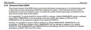
    However, the same technique fails on F5252 part even though the address for PMMCTL0 is the same.

    Maybe there is some difference of protocol with Flash device and FRAM device, please refers to below user guide:

    https://www.ti.com/lit/ug/slau319af/slau319af.pdf?ts=1709871960334

    It also describes two method for exit bsl mode:

    B.R.

    Sal

  • Thank you Sal. I'll leave this post open for a bit, and will close it when we narrow down to the final solution. The reset at the exit of BSL is crucial, not so much for the convenience of remote upgrade, but to preserve data integrity in flash.

  • Sure, I will keep the thread open.

  • Probably it will be worth confirming the following:

    • Setting the PC to the address located at the vector 0xFFFE does not cause a PUC/POR/BOR reset in MCU. The address at 0xFFFE is the entry point of the user's software.
    • There is no address to jump (or to set the PC in the BSL scripter) to cause a PUC/POR/BOR reset. Hence:
    • The only ways to cause a reset in MCU are:
      • Hardware reset through the reset pin.
      • Placing a wrong password or a value in a register (Watchdog or PMMCTL0)
      • some other way?
    • Running the user's code after the BSL programming is not safe, because many registers for peripherals are modified for BSL usage.
    • The only safe way to run the user's code after the BSL programming is either a power cycle or to cause a PUC/POR/BOR reset.


  • Hi Arsen,

    Yes, it is a software reset wihtout BOR reset in MCU, it is usually used for jump into applicaion code.

    To trigger BOR, I suppose there is some way in the code:

    B.R.

    Sal

  • Hi Arsen,

    Haven't heard an update from you in a while. I assume there is no pending issue and I'll close this thread. 

    If you have further question, you can directly reply here and the thread will open automatically. Or you can file a new thread. Thanks!

    B.R.

    Sal

  • Please do. Thank you!

**Attention** This is a public forum