This thread has been locked.

If you have a related question, please click the "Ask a related question" button in the top right corner. The newly created question will be automatically linked to this question.

MSP430FR6043: LCD segments dim or turn off when additional segments are turned on

Part Number: MSP430FR6043
Other Parts Discussed in Thread: EVM430-FR6043

We are using a new custom LCD and board and the built in LCD drivers in the micro. 

We can urn on individual segments with no issue and even 8 or 10, but as we turn on more and more segments, some of the segments start to fade or disappear completely. It appears that many of the dimmed segments are on the same common line. 

Any ideas what would cause this?  Does it have to do with voltages? Or perhaps the way we have configured the drivers? 

Any thoughts are appreciated. 

  • Can you test the LCD wave to see what happens? Maybe the drive voltage is too low after adding more segment.

  • We haven't had a chance to do that.  Trying to figure out how to hook a scope up to such small parts (always tricky). 

    However, we did play with the refresh rate by messing with the LCD clock settings. 

    When we slowed down the refresh rate, the issue decreased.  We found a setting that is close to working, but when all segments are on, some of them are a slightly different color.  If we slow the clock down any more, we start to notice flickering. 

    What does this indicate?  Is there a hardware change we could look at to fix this issue rather than just slowing the refresh rate down? I want to make sure that we have a robust solution that will work with variances in displays and boards. 

    My understanding is that by slowing the refresh rate down, we have decreased the current demand.  Is that correct?  How else is current controlled in this situation?   

    To add a little more detail...  We started with the TI EVM430-FR6043 board and have been developing on it for a few months.  The display on that board has almost twice as many segments as our display.  We copied the voltage ladder from the TI board directly for our board.  Power is supplied by 2 AA batteries.

    Any additional information is appreciated.   

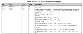
  • Have you try to increase the charge pump voltage? If you can't test, please make a try on the code first. Changing the blink frequency can reduce the loading to the charge pump, which can keep the voltage higher, but if it is too slow, human eyes can see the blink.

  • We are using an external resister ladder.  We can change out the resisters I guess in the ladder, but not sure which way to go. 

    I'm struggling to understand why some of the segments looked fine and others were off or very dim.  Why are all the segments not affected the same way. 

  • If you can share the wave, I can give more insight. Actually, I don't meet this kind of porblem, some part is OK, some is not.

**Attention** This is a public forum