Other Parts Discussed in Thread: BQ78350, , TIDA-00449, BQ76930, MSP-TS430DA38
Hey TI Experts, I was working with MSP430G2955 and BQ78350 in a bms board .I'm working on the firmware of this. I got a code from TIDA-00449 software support part. I'm trying to read the voltage and current from the cells in this code. i have initialized the I2C bus according to on of the examples that we got from the TI website.
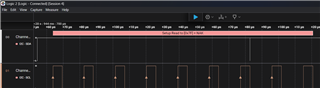
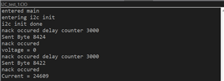
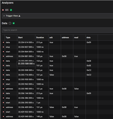
I took reference of the I2C send and receive codes from drv_i2c.c from design help from TIDA-00449. I also put in some print statements to check where the issue was. I have attached the code that i have below along with the output.
Also if you have any other suggestions for the codes that could be used for reference, please let me know.
Kindly help me with this.
PS. MSP is the master and BQ78350 is the slave.
#include <stdio.h>
#include <inttypes.h>
#include <msp430.h>
#include <driverlib.h>
#include <string.h>
#include "drv_i2c.h"
#include "drv_bq76930.h"

#define DELAY_LIMIT1 10
unsigned char *ptr_rx;
unsigned char RXByte[100];
unsigned char Slave_Address1 = 0x17;

// COMMANDS

#define REMAININGCAP 0X01
#define REMAININGTIME 0X02
#define BATTERYMODE 0X03
#define ATRATE 0X04
#define ATRATETIMETOFULL 0X05
#define ATRATETIMETOEMPTY 0X06
#define ATRATEOK 0X07
#define TEMPERATURE 0X08
unsigned char VOLTAGE = 0x09;
unsigned char CURRENT = 0X0A;
#define AVGCURRENT 0X0B
#define MAXERROR 0X0C
#define RELATIVESOC OXOD
#define REMAININGCAPACITY 0X0E
#define FULLCHARGECAPACITY 0X10
#define RUNTIMETOEMPTY 0X11
#define AVGTTE 0X12
#define AVGTTF 0X13
#define CHARGINGCURRENT 0X14
#define CHARGINGVOLTAGE 0X15
#define BATTERYSTATUS 0X16
#define CYCLECOUNT 0X17
#define DESIGNCAPACITY 0X18
#define DESIGNVOLTAGE 0X19
#define SPECSINFO 0X1A
#define MFGDATA 0X1A
#define SOH 0X4F
#define SAFETYALERT 0X50
#define SAFETYSTATUS 0X51
#define PFALERT 0X52
#define PFSTATUS 0X52

typedef struct
{
int nI2C;
unsigned char nAddress;
} TI2C;

void i2c_init();
int I2CSendByte(unsigned char I2CSlaveAddress, unsigned char data);
int I2CSendBytes(unsigned char I2CSlaveAddress, unsigned char *DataBuffer, unsigned int ByteCount, unsigned int *SentByte);
int I2CWriteRegisterByte(unsigned char I2CSlaveAddress, unsigned char Register, unsigned char Data);
int I2CWriteRegisterByteWithCRC(unsigned char I2CSlaveAddress, unsigned char Register, unsigned char Data);
int I2CWriteRegisterWordWithCRC(unsigned char I2CSlaveAddress, unsigned char Register, unsigned int Data);
int I2CWriteBlockWithCRC(unsigned char I2CSlaveAddress, unsigned char StartAddress, unsigned char *Buffer, unsigned char Length);
int I2CWriteRegisterWord(unsigned char I2CSlaveAddress, unsigned char Register, unsigned int Data);
int I2CReadBytes(unsigned char I2CSlaveAddress, unsigned char *DataBuffer, unsigned int ExpectedByteNumber, unsigned int *NumberOfReceivedBytes);
int I2CReadRegisterByte(unsigned char I2CSlaveAddress, unsigned char Register, unsigned char *Data);
int I2CReadBlock(unsigned char I2CSlaveAddress, unsigned char StartRegisterAddress, unsigned char *Buffer, unsigned int BlockSize, unsigned int *NumberOfBytes);
unsigned char CRC8(unsigned char *ptr, unsigned char len,unsigned char key);
int I2CReadRegisterByteWithCRC(unsigned char I2CSlaveAddress, unsigned char Register, unsigned char *Data);
int I2CReadRegisterWordWithCRC(unsigned char I2CSlaveAddress, unsigned char Register, unsigned int *Data);
int I2CReadBlockWithCRC(unsigned char I2CSlaveAddress, unsigned char Register, unsigned char *Buffer, unsigned char Length);

int main(void)
{
    printf("entered main \n");
    WDTCTL = WDTPW | WDTHOLD;   // stop watchdog timer
                            // Set DCO to 16MHz
    DCOCTL |= (BIT6+BIT5) ;
    DCOCTL &= ~BIT7;
    DCOCTL &= ~(MOD0+MOD1+MOD2+MOD3+MOD4);

    BCSCTL1 |= (RSEL0+RSEL1+RSEL2+RSEL3);
    BCSCTL2 &= ~BIT3;

    i2c_init();

    unsigned int curr, voltage;
    unsigned int voltage2;

    if(I2CReadRegisterWordWithCRC(Slave_Address1, VOLTAGE , &voltage)== 0)
        printf("voltage = %c \n",voltage);
    else
        printf("unable to read");
    if(I2CReadRegisterWordWithCRC(Slave_Address1, VOLTAGE , &voltage2) < 0)
        printf("I2C error \n");
    else
        printf("voltage = %c \n",voltage2);
    printf(I2CReadRegisterWordWithCRC(Slave_Address1, CURRENT, &curr));
    printf("current = %c \n",curr);
    return 0;
}

void i2c_init()
{
    printf("entering i2c init \n");

    P3SEL |= BIT1;
    P3SEL |= BIT2;
//    P3SEL2 &= (~BIT1);
//    P3SEL2 &= (~BIT2);

    UCB0CTL1 |= UCSWRST;       // SWRST SET


    UCB0CTL0 |= UCMODE_3;      // CHOOSE I2C MODE
    UCB0CTL0 |= UCMST;         //CHOOSE MASTER MODE
    UCB0CTL0 |= UCSYNC;        //enable synchronous mode

    UCB0CTL1 = UCSSEL_2 | UCSWRST;       //CHOOSE SMCLK

    UCB0BR0 = 12;                //CHOOSE PRESCALER VALUEwhere SMCLK =16MHz, 16000000/16 = 1Mhz
    UCB0BR1 = 0;

    //UCB0CTL1 |= UCTR;          //CHOOSE TRANSMITTER MODE
    UCB0I2CSA |= Slave_Address1;          //set slave address

    UCB0CTL1 &= ~UCSWRST;        //CLEAR SWRST
    UCB0I2CIE |= UCSTTIE;
    IE2 |= UCB0TXIE;
    printf("i2c init done \n");
}

int I2CSendByte(unsigned char I2CSlaveAddress, unsigned char data)
{
    unsigned long int DelayCounter = 0;

    UCB0CTL0 |= UCMST;
    UCB0I2CSA = I2CSlaveAddress;

     UCB0CTL1 |= UCTR; //data in transmit direction
     UCB0CTL1 |= UCTXSTT; //Generate Start Condition
                          //Send Start Byte

     while(!(IFG2 & UCB0TXIFG))  //if UCB0TXIFG != 0, wait here
     {
         DelayCounter ++;
         if (DelayCounter >= DELAY_LIMIT)
             break;
     }

     if (DelayCounter >= DELAY_LIMIT)
     {
         return -1;
     }

     UCB0TXBUF = data;
     // send the data

     DelayCounter = 0;

     while(DelayCounter < DELAY_LIMIT && !(IFG2 & UCB0TXIFG))
     {
         DelayCounter++;
     }

     if (DelayCounter >= DELAY_LIMIT)
     {
         return -1;
     }

     UCB0CTL1 |= UCTXSTP;           //send stop bit

     DelayCounter = 0;

     while(DelayCounter < DELAY_LIMIT && (UCB0CTL1 & UCTXSTP))
     {
         DelayCounter++;
     }

     if (DelayCounter >= DELAY_LIMIT)
     {//check if NACK condition occurred
         return -1;

     }

     else
         return 0;

}

int I2CSendBytes(unsigned char I2CSlaveAddress, unsigned char *DataBuffer, unsigned int ByteCount, unsigned int *SentByte)
{
    unsigned long int DelayCounter = 0;
    unsigned int NumberOfBytesSent = 0;
    unsigned char *DataPointer;

    UCB0CTL0 |= UCMST;
    UCB0I2CSA = I2CSlaveAddress;
    IE2 |= UCB0TXIE;

     DataPointer = DataBuffer;
     UCB0CTL1 |= UCTR; //data in transmit direction
     UCB0CTL1 |= UCTXSTT; //Generate Start Condition
                          //Send Start Byte

     while(!(IFG2 & UCB0TXIFG))  //if UCTXSTT != 0, wait here
     {
         DelayCounter ++;
         if (DelayCounter > DELAY_LIMIT)
             break;
     }

     if (DelayCounter >= DELAY_LIMIT)   //check if NACK condition occurred
     {
         *SentByte = NumberOfBytesSent;
         printf(" number of bytes sent %d \n", NumberOfBytesSent);
         UCB0CTL1 |= UCTXSTP;
         return -1;
     }

     for(NumberOfBytesSent = 0; NumberOfBytesSent < ByteCount; NumberOfBytesSent++)
     {
         UCB0TXBUF= *DataPointer;
         printf(" data pointer %c \n", DataPointer);
         DelayCounter = 0;

         while(DelayCounter < DELAY_LIMIT && (!(IFG2 & UCB0TXIFG) || (UCB0CTL1 & UCTXSTT))) //check if the byte has been sent
         {
             DelayCounter++;
         }
         printf("byte sent %ld 1 \n",DelayCounter);
         if (DelayCounter >= DELAY_LIMIT)   //check if NACK condition occurred
         {
             printf("nack occured delay counter %ld \n",DelayCounter);

             *SentByte = NumberOfBytesSent;
             printf("Sent Byte %d \n", SentByte);
             UCB0CTL1 |= UCTXSTP;
             printf("nack occured \n");
             //send stop condition
             return -1;
         }

         DataPointer++;
     }

     IFG2 &= ~UCB0TXIFG;
     UCB0CTL1 |= UCTXSTP;       //send stop bit

     DelayCounter = 0;

     while(DelayCounter < DELAY_LIMIT && ((UCB0CTL1 & UCTXSTP)))
     {
         DelayCounter++;
     }

     *SentByte =  NumberOfBytesSent;

     if (DelayCounter >= DELAY_LIMIT)   //check if NACK condition occurred
     {
         UCB0CTL1 |= UCSWRST;
         return -1;
     }
     else
         return 0;
}

int I2CWriteRegisterByte(unsigned char I2CSlaveAddress, unsigned char Register, unsigned char Data)
{
    unsigned char DataBuffer[2];
    unsigned int SentByte = 0;


    DataBuffer[0] = Register;
    DataBuffer[1] = Data;

    return(I2CSendBytes(I2CSlaveAddress, DataBuffer, 2, &SentByte));
}

int I2CWriteRegisterByteWithCRC(unsigned char I2CSlaveAddress, unsigned char Register, unsigned char Data)
{
    unsigned char DataBuffer[4];
    unsigned int SentByte = 0;

    DataBuffer[0] = I2CSlaveAddress << 1;
    DataBuffer[1] = Register;
    DataBuffer[2] = Data;
    DataBuffer[3] = CRC8(DataBuffer, 3, CRC_KEY);

    return(I2CSendBytes(I2CSlaveAddress, DataBuffer + 1, 3, &SentByte));
}

int I2CWriteRegisterWordWithCRC(unsigned char I2CSlaveAddress, unsigned char Register, unsigned int Data)
{
    unsigned char DataBuffer[6];
    unsigned int SentByte = 0;

    DataBuffer[0] = I2CSlaveAddress << 1;
    DataBuffer[1] = Register;
    DataBuffer[2] = LOW_BYTE(Data);
    DataBuffer[3] = CRC8(DataBuffer, 3, CRC_KEY);
    DataBuffer[4] = HIGH_BYTE(Data);
    DataBuffer[5] = CRC8(DataBuffer + 4, 1, CRC_KEY);

    return(I2CSendBytes(I2CSlaveAddress, DataBuffer + 1, 5, &SentByte));
}

int I2CWriteBlockWithCRC(unsigned char I2CSlaveAddress, unsigned char StartAddress, unsigned char *Buffer, unsigned char Length)
{
    unsigned char *BufferCRC, *Pointer;
    int i;
    unsigned int SentByte = 0;
    int result;

    BufferCRC = (unsigned char*)malloc(2*Length + 2);
    if (NULL == BufferCRC)
        return -1;

    Pointer = BufferCRC;
    *Pointer = I2CSlaveAddress << 1;
    Pointer++;
    *Pointer = StartAddress;
    Pointer++;
    *Pointer = *Buffer;
    Pointer++;
    *Pointer = CRC8(BufferCRC, 3, CRC_KEY);

    for(i = 1; i < Length; i++)
    {
        Pointer++;
        Buffer++;
        *Pointer = *Buffer;
        *(Pointer + 1) = CRC8(Pointer, 1, CRC_KEY);
        Pointer++;
    }

    result = I2CSendBytes(I2CSlaveAddress, BufferCRC + 1, 2*Length + 1, &SentByte);

    free(BufferCRC);
    BufferCRC = NULL;

    return result;
}

int I2CWriteRegisterWord(unsigned char I2CSlaveAddress, unsigned char Register, unsigned int Data)
{
    unsigned char DataBuffer[3];
    unsigned int SentByte = 0;

    DataBuffer[0] = Register;
    DataBuffer[1] = LOWBYTE(Data);
    DataBuffer[2] = HIGHBYTE(Data);

    return(I2CSendBytes(I2CSlaveAddress, DataBuffer, 3, &SentByte));
}

int I2CReadBytes(unsigned char I2CSlaveAddress, unsigned char *DataBuffer, unsigned int ExpectedByteNumber, unsigned int *NumberOfReceivedBytes)
{
    unsigned long int DelayCounter = 0;
    unsigned char *DataPointer;
    unsigned int *NumberOfReceivedBytesPointer;

    NumberOfReceivedBytesPointer = NumberOfReceivedBytes;
    *NumberOfReceivedBytesPointer = 0;

    UCB0CTL0 |= UCMST;
    DataPointer = DataBuffer;
    UCB0I2CSA = I2CSlaveAddress;

    UCB0CTL1 &= ~(UCTR); //data in receive direction

    UCB0CTL1 |= UCTXSTT; //Generate Start Condition

     while((UCB0CTL1 & UCTXSTT)
             )  //if UCTXSTT != 0, wait here
     {
         DelayCounter ++;
         if (DelayCounter >= DELAY_LIMIT)
             break;
     }

     if (DelayCounter >= DELAY_LIMIT || UCB0STAT & UCNACKIFG)   //check if NACK condition occurred
         return -1;

     for(*NumberOfReceivedBytesPointer = 0; *NumberOfReceivedBytesPointer < ExpectedByteNumber; (*NumberOfReceivedBytesPointer)++)
     {
         if(*NumberOfReceivedBytesPointer + 1 == ExpectedByteNumber)
             UCB0CTL1 |= UCTXSTP;

         DelayCounter = 0;

         while(DelayCounter < DELAY_LIMIT && !(IFG2 & UCB0RXIFG))
         {
             DelayCounter++;
         }

         if(DelayCounter == DELAY_LIMIT)
         {
             UCB0CTL1 |= UCSWRST;   //if I2C overtime condition occurred, reset I2C engine
             return -1;
         }

         *DataPointer = UCB0RXBUF;

         DataPointer++;
     }

     DelayCounter = 0;
     while(DelayCounter < DELAY_LIMIT && (UCB0CTL1 & UCTXSTP))
     {
         DelayCounter++;
     }

     if(DelayCounter >= DELAY_LIMIT)
     {
         UCB0CTL1 |= UCSWRST;
         return -1;
     }

     return 0;

}

int I2CReadRegisterByte(unsigned char I2CSlaveAddress, unsigned char Register, unsigned char *Data)
{
    unsigned char TargetRegister = Register;
    unsigned int SentByte = 0;
    unsigned int ReadDataCount = 0;
    int ReadStatus = 0;
    int WriteStatus = 0;

    WriteStatus = I2CSendBytes(I2CSlaveAddress, &TargetRegister, 1, &SentByte);

    ReadStatus = I2CReadBytes(I2CSlaveAddress, Data, 1, &ReadDataCount);

    if (ReadStatus != 0 || WriteStatus != 0)
    {
        return -1;
    }

    return 0;
}

int I2CReadBlock(unsigned char I2CSlaveAddress, unsigned char StartRegisterAddress, unsigned char *Buffer, unsigned int BlockSize, unsigned int *NumberOfBytes)
{
    unsigned char TargetRegister = StartRegisterAddress;
    unsigned int SentByte = 0;
    int ReadStatus = 0;
    int WriteStatus = 0;

    WriteStatus = I2CSendBytes(I2CSlaveAddress, &TargetRegister, 1, &SentByte);

    ReadStatus = I2CReadBytes(I2CSlaveAddress, Buffer, BlockSize, NumberOfBytes);

    if(ReadStatus != 0 || WriteStatus != 0)
    {
        return -1;
    }

    return 0;
}

unsigned char CRC8(unsigned char *ptr, unsigned char len,unsigned char key)
{
    unsigned char i;
    unsigned char crc=0;
    while(len--!=0)
    {
        for(i=0x80; i!=0; i/=2)
        {
            if((crc & 0x80) != 0)
            {
                crc *= 2;
                crc ^= key;
            }
            else
                crc *= 2;

            if((*ptr & i)!=0)
                crc ^= key;
        }
        ptr++;
    }
    return(crc);
}

int I2CReadRegisterByteWithCRC(unsigned char I2CSlaveAddress, unsigned char Register, unsigned char *Data)
{
    unsigned char TargetRegister = Register;
    unsigned int SentByte = 0;
    unsigned char ReadData[2];
    unsigned int ReadDataCount = 0;
    unsigned char CRCInput[2];
    unsigned char CRC = 0;
    int ReadStatus = 0;
    int WriteStatus = 0;
    printf("CRC Read \n");
    WriteStatus = I2CSendBytes(I2CSlaveAddress, &TargetRegister, 1,  &SentByte);
    printf("write status %d \n",WriteStatus);

    ReadStatus = I2CReadBytes(I2CSlaveAddress, ReadData, 2, &ReadDataCount);
    printf("read status %d \n", ReadStatus);

    if (ReadStatus != 0 || WriteStatus != 0)
    {
        printf("Reading error \n");
        return -1;
    }

    printf("readdata %c %c \n", ReadData[0], ReadData[1]);

    CRCInput[0] = (I2CSlaveAddress << 1) + 1;

    printf("crcinput0 %c \n", CRCInput[0]);

    CRCInput[1] = ReadData[0];
    printf("crcinput 1 %c \n",CRCInput[1]);

    CRC = CRC8(CRCInput, 2, CRC_KEY);
    printf("CRC = %c \n ", CRC);

    if (CRC != ReadData[1])
    {
        printf("CRC Error \n");
        return -1;

    }


    *Data = ReadData[0];
    return 0;
}

int I2CReadRegisterWordWithCRC(unsigned char I2CSlaveAddress, unsigned char Register, unsigned int *Data)
{
    unsigned char TargetRegister = Register;
    unsigned int SentByte = 0;
    unsigned char ReadData[4];
    unsigned int ReadDataCount = 0;
    unsigned char CRCInput[2];
    unsigned char CRC = 0;
    int ReadStatus = 0;
    int WriteStatus = 0;

    WriteStatus = I2CSendBytes(I2CSlaveAddress, &TargetRegister, 1, &SentByte);

    ReadStatus = I2CReadBytes(I2CSlaveAddress, ReadData, 4, &ReadDataCount);

    if (ReadStatus != 0 || WriteStatus != 0)
    {
        return -1;
    }

    CRCInput[0] = (I2CSlaveAddress << 1) + 1;
    CRCInput[1] = ReadData[0];

    CRC = CRC8(CRCInput, 2, CRC_KEY);

    if (CRC != ReadData[2])
        return -1;

    CRC = CRC8(ReadData + 2, 1, CRC_KEY);

    if (CRC != ReadData[3])
        return -1;

    *Data = ReadData[0];

    *Data = (*Data << 8) + ReadData[1];

    return 0;
}

int I2CReadBlockWithCRC(unsigned char I2CSlaveAddress, unsigned char Register, unsigned char *Buffer, unsigned char Length)
{
    unsigned char TargetRegister = Register;
    unsigned int SentByte = 0;
    unsigned char *ReadData = NULL, *StartData = NULL;
    unsigned int ReadDataCount = 0;
    unsigned char CRCInput[2];
    unsigned char CRC = 0;
    int ReadStatus = 0;
    int WriteStatus = 0;
    int i;

    StartData = (unsigned char *)malloc(2 * Length);

    if (NULL == StartData)
        return -1;

    ReadData = StartData;

    WriteStatus = I2CSendBytes(I2CSlaveAddress, &TargetRegister, 1, &SentByte);

    ReadStatus = I2CReadBytes(I2CSlaveAddress, ReadData, 2 * Length, &ReadDataCount);

    if (ReadStatus != 0 || WriteStatus != 0)
    {
        free(StartData);
        StartData = NULL;

        return -1;
    }

    CRCInput[0] = (I2CSlaveAddress << 1) + 1;
    CRCInput[1] = *ReadData;

    CRC = CRC8(CRCInput, 2, CRC_KEY);

    ReadData++;
    if (CRC != *ReadData)
    {
        free(StartData);
        StartData = NULL;
        return -1;
    }
    else
        *Buffer = *(ReadData - 1);

    for(i = 1; i < Length; i++)
    {
        ReadData++;
        CRC = CRC8(ReadData, 1, CRC_KEY);
        ReadData++;
        Buffer++;

        if (CRC != *ReadData)
        {
            free(StartData);
            StartData = NULL;

            return -1;
        }
        else
            *Buffer = *(ReadData - 1);
    }

    free(StartData);
    StartData = NULL;

    return 0;
}
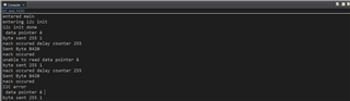
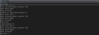
OUTPUT :