This thread has been locked.

If you have a related question, please click the "Ask a related question" button in the top right corner. The newly created question will be automatically linked to this question.

MSP430FR6043: Gas Flow Meter - Random Delta TOF spikes - how do we fix?

Part Number: MSP430FR6043

We are bringing online our own boards and sensor bodies and seeing issues we didn't see with the dev board and 3D printed sensors we were using.  We are using the same transducers and the sensor bodies are essentially the same.  Transducers are 300 kHz.

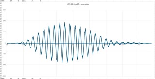
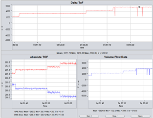
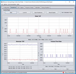
The first image shows the running data and the spikes we are seeking.  This is with gas flowing through the sensor. Gas flow is controlled by a flow meter so it is very consistent.   The spikes are fairly large.

.
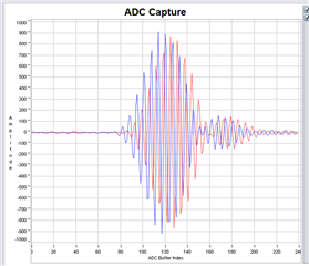
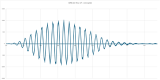
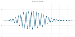
The next set of images show the Up and Down waveforms superimposed on each other.  This is at least 7 passes.  They look very consistent and clean to us.  At least 1 of the seven waves corresponds to a spike in the Delta TOF. 
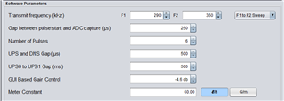
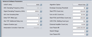
We are using these settings currently.  
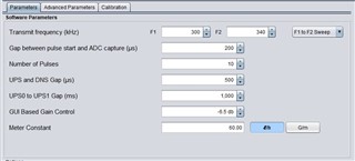
Is this a tuning issue or something with the Algorithm setup, or is there some other issue we are fighting?   Looking for help knowing where to focus our efforts. 

Any help is greatly appreciated. 

  • Hi Brent,

    Do you have images of what your ADC captures looked like before moving to the custom hardware? 

    Your current ADC capture does look relatively good with low noise, I am wondering if the slow rise in signal amplitude could be the problem. Those spikes in your dTOF and VFR are typically caused by problems with the algorithms correlation result. 

    Typically in our examples the amplitude shown in the ADC capture rises more rapidly.

    Maybe a quick test to try would also be to increase the number of pulses to see how this affects the waveform and your results.

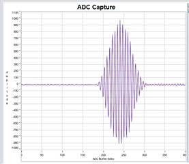
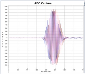
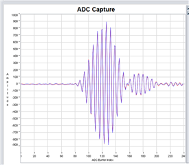
  • I think my prior images were a little miss-leading due to the scaling in the Excel plots.  Below are images from the TI Software.  The curves for our new sensor rise just as quickly as our older 3D printed sensor.  The images below are for our new sensor, using the TI software.  The first one is with no flow, the second is with our max flow.  How do these look?  Again, they are very similar to our first setup. 

    What do you mean by the “algorithm correlation results”.  Do we have any control over any parameters for this?  The algorithms are a bit of a black box.

    How do the signal amplitudes affect the algorithms?

    Where else should we be looking?  Glad to provide more details if there is something that will be helpful. 

    .  Please ask them what he means by  “algorithm correlation results” and if we have any control over that.

  • Also, for the Delta ToF algorithms, what characteristics of the data are the most important?  We don't fully understand how the algorithms work.  Is there any additional resources that provide more details on how they work?

  • Hi Brent,

    Thank you for the information and updated images.

    These new images look very good. The captures appear good with low noise. Honestly it is surprising to see that you are having bad results. Usually, those spikes in the delta time of flight are caused by an incorrectly set maximum correlation point, typically due to noise. 

    Could you additionally post an image of your advanced parameters window? Maybe something there will shed some light on the problem.

    You may want to experiment by adjusting the number of pulses. Considering you are getting good signal amplitude, I would suggest to try reducing the number first and seeing if this helps. Another setting that I sometimes see helping is to reduce the ADC capture duration and increase the gap between pulse start and ADC capture, so most of the captured signal is the active waveform, with less of the flat signal before and after the pulsing. This is just something to experiment with, not a surefire fix.

    Also, sorry about the lack of clarity when I say algorithm correlation results. The algorithm is intentionally mostly a black box, but we do have some more detailed information about how it works to give an overview. You can read about it a bit in the MSP430 USS Academy.

  • We tried reducing the ADC capture duration and increasing the gap between pulse start and ADC capture.  This seems to improve (fewer spikes) for most of the units we are testing.  We tried reducing the pulse count from 8 to 6.  This reduced spikes on some units and increased it on other units.  Some units behave better when the pulse count is higher, like 10. Even with a smaller capture window, we still get spikes at flows near the top end of our flow range (9-10 L/min).

     We have done extensive testing altering sweep frequencies, pulse count.  Some settings reduce the spikes, but nothing gets rid of them completely.

     Here are some sample data.  I don't know why they are so blurry after I insert them.

    These data step through flow as follows: 4, 6, 8, 10 L/min.

    10 L/min (our maximum flow rate)

    0 L/min

  • I'm glad to hear things are getting closer. Unfortunate that the spikes are coming in just at the top of your flow rate range.

    When you get those spikes, are you getting any errors from the device? It looks like they are jumping all the way down to the initial 2000 ns dToF. Your waveforms in the ADC capture look quite good. This is leading me to think that there is not much left to do with the configuration settings. If you haven't already, you could try increasing the gap between pulse start and ADC capture further, and decreasing the capture window further as well. 

    The quality of the ADC captures also suggests to me that this isn't a hardware issue. Unless you are getting some sporadic bad captures, I don't think the signal quality, or its reception, is causing the problem. Try the above and in the mean time I will ask some of my colleagues if there are any other suspect factors here.

  • Thanks Dylan.  I have tried reducing the ADC capture until only the envelope is captured.  It didn't improve much compared to the settings I gave in yesterday's post, and I couldn't use such a narrow window long term anyway because due to the temperture and gas composition range over which this device is expected to operate. (All the testing so far,a nd the observed spikes, has been done with air at room temp.)

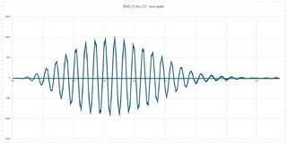
    I don't think we are getting a sporadic bad capture because I collected ADC captures until I got a spike and plotted them on top of each other.  None of them looked like an outlier.  The following chart represents 7 captures ploted on top of each other, one of which had a spike in the Delta TofF.  The strange thing, is I can affect how often it spikes by anything that reduces noise.  For example, if I shield the whole sensor with grounded foil, the spikes reduce.  If I mess with the design of the inlet to reduce turbulence, the spikes reduce. 

    None of these  completely solve the problem, and it is inconsistent from unit to unit.  On one unit, I made a wiring change to pulse the transudcers with 3.3V instead of 5V.  This almost completely elimimated the spikes.  The next day I tested that exact same setup and the spikes were back, so it seems like there is some uncontrolled variable that I am unaware of.  Or the setup is on the verge of spikes and minor randome variations in noise, temperature, whatever, are causing it to move into whatever is causing the spikes.

    It does seem to be a lot like the sample slipping example.  One bit of information that might help: I have tested setups that spike even at low flows like 4 L/min.  In such cases the spike is about the same size and results in a negative Delta TofF.  Also, I can mess with settings until the "spiking" is continuous and it periodically spikes to the correct value.

  • Thanks for the information. I agree that it sounds like you aren't getting a sporadic bad ADC capture. My colleague's first suggestion was to try lowering the signal sampling frequency, first try 1.7M, and move slowly down to 1MSps to see if this helps to reduce or remove the dToF spikes. Please let me know if that helps here.

  • We'll try that.  Any way to make the ultrasonic sensing design center app do rates between 1 MHz and 2 MHz?  Or do we have to just modify the header file?  Makes it very slow to try out other parameters if we have to edit, recompile, reprogram each time.

  • Hey Dylan, we are having trouble figuring out how to change the signal sampling frequency to something other than 1MHz and 2MHz using the design center.

    The capture over sample rate is configured by setting the variable ussCaptureConfig.overSampleRate.

    The configured values are limited by the following definition :


    //! \brief Configures SDHS Over Sample Rate

    //!    \n \n <b>Registers modified:</b> <i>SDHS.CTL0.OBR</i>

    typedef enum _USS_Capture_Over_Sample_Rate_ {

                    USS_Capture_Over_Sample_Rate_10 = 0x0000,

                    //!< Configures SDHS Over Sample Rate to 10

                    USS_Capture_Over_Sample_Rate_20 = 0x0001,

                    //!< Configures SDHS Over Sample Rate to 20

                    USS_Capture_Over_Sample_Rate_40 = 0x0002,

                    //!< Configures SDHS Over Sample Rate to 40

                    USS_Capture_Over_Sample_Rate_80 = 0x0003,

                    //!< Configures SDHS Over Sample Rate to 80

                    USS_Capture_Over_Sample_Rate_160 = 0x0004

                    //!< Configures SDHS Over Sample Rate to 160 } USS_Capture_Over_Sample_Rate;


    USS_PLL_FREQ is set based on the following definitions:


    #if (USS_HSPLL_FREQ_IN_MHZ == 80)

    #define    USS_HSPLL_FREQ    USS_HSPLL_output_clk_freq_80_MHz

    #define USS_PLL_FREQ                80e6

    #elif (USS_HSPLL_FREQ_IN_MHZ == 79)

    #define    USS_HSPLL_FREQ    USS_HSPLL_output_clk_freq_79_MHz

    #define USS_PLL_FREQ                79e6

    #elif (USS_HSPLL_FREQ_IN_MHZ == 78)

    #define    USS_HSPLL_FREQ    USS_HSPLL_output_clk_freq_78_MHz

    #define USS_PLL_FREQ                78e6

    #elif (USS_HSPLL_FREQ_IN_MHZ == 77)

    #define    USS_HSPLL_FREQ    USS_HSPLL_output_clk_freq_77_MHz

    #define USS_PLL_FREQ                77e6

    #elif (USS_HSPLL_FREQ_IN_MHZ == 76)

    #define    USS_HSPLL_FREQ    USS_HSPLL_output_clk_freq_76_MHz

    #define USS_PLL_FREQ                76e6

    #elif (USS_HSPLL_FREQ_IN_MHZ == 75)

    #define    USS_HSPLL_FREQ    USS_HSPLL_output_clk_freq_75_MHz

    #define USS_PLL_FREQ                75e6

    #elif (USS_HSPLL_FREQ_IN_MHZ == 74)

    #define    USS_HSPLL_FREQ    USS_HSPLL_output_clk_freq_74_MHz

    #define USS_PLL_FREQ                74e6

    #elif (USS_HSPLL_FREQ_IN_MHZ == 73)

    #define    USS_HSPLL_FREQ    USS_HSPLL_output_clk_freq_73_MHz

    #define USS_PLL_FREQ                73e6

    #elif (USS_HSPLL_FREQ_IN_MHZ == 72)

    #define    USS_HSPLL_FREQ    USS_HSPLL_output_clk_freq_72_MHz

    #define USS_PLL_FREQ                72e6

    #elif (USS_HSPLL_FREQ_IN_MHZ == 71)

    #define    USS_HSPLL_FREQ    USS_HSPLL_output_clk_freq_71_MHz

    #define USS_PLL_FREQ                71e6

    #elif (USS_HSPLL_FREQ_IN_MHZ == 70)

    #define    USS_HSPLL_FREQ    USS_HSPLL_output_clk_freq_70_MHz

    #define USS_PLL_FREQ                70e6

    #elif (USS_HSPLL_FREQ_IN_MHZ == 69)

    #define    USS_HSPLL_FREQ    USS_HSPLL_output_clk_freq_69_MHz

    #define USS_PLL_FREQ                69e6

    #elif (USS_HSPLL_FREQ_IN_MHZ == 68)

    #define    USS_HSPLL_FREQ    USS_HSPLL_output_clk_freq_68_MHz

    #define USS_PLL_FREQ                68e6

    #else

    #define    USS_HSPLL_FREQ    USS_HSPLL_output_clk_freq_80_MHz

    #define USS_PLL_FREQ                80e6

    #endif


    Question : Is USS_HSPLL_FREQ_IN_MHZ fixed at 80, or is it adjusted from

    68 to 80

    per the definitions above, along with a modified ussCaptureConfig.overSampleRate to set the sampling frequency?

  • You have the Envelope Crossing Threshold set to 50%. The threshold ends up landing between two lobes which means the algorithm will cycle slip.

    EDIT: This criticism only valid for water meters. Gas meters perform a Hilbert transform and instead compute based off of the envelope.

  • Thanks Seth.  Please help me understand this better.  Couldn't that happen at any  threshold level that is near the top of one of the lobes? Also, from what I have read in the TI documentation, I thought the algorim does a curve fit to the peaks of each lobe before applying the crossing threshold, specifically to avoid that problem.

  • Yes, sorry, I am used to dealing with water meters where the threshold locks onto an individual lobe. I will edit my previous message to reflect that.

  • Hi Brent,

    Sorry for the slow answer here.

    USS_HSPLL_FREQ_IN_MHZ is adjusted based on the definitions above. The stipulation is that you must make sure that you final values for signal sampling frequency, PLL frequency, and oversampling rate keep the equation:

    Sampling frequency = (PLL Frequency)/(Oversampling rate)

    This equation is found in the USS Design Center User's Guide PDF. You will need to edit all of these outside of the USS GUI in order to get the exact values you want. As you've noticed, the USS GUI will stop you from editing certain variables now and makes them read only, in an attempt to help keep other customers from misconfiguring the device. 

  • Dylan, thank you for your comment.  We managed to get the header file configured properly to give us other signal sampling frequencies.  We were aware of the relationaship among PLL, Sampling Freq. and OSR and have been adhering to it.  And yet, we can't seem to get the ToF algorithms to perform reliably.  We have tried 1.0, 1.2, 2.0, 3.4 MHz signal sampling rate, each with various combinations of pulse count and frequency scan.

  • Still not having success with TIs algorithm.  We think the tracking portion of the algorithm is getting  confused.  Is there a way to disable tracking and force it to acquire every time? 

  • I am not familiar with a tracking portion of the algorithm, I might be able to help with this if you could explain a bit further what you are looking for here. Reading up on it more, I am mostly seeing tracking algorithms in the sense of predictive tracking. 

    HoweverI will sayt that I am not aware of any setting in the USS GUI or in the source code that will allow you to change the algorithm to change this.

  • Hi Brent,

    You can disable tracking by going to the advanced parameters tab in the USS GUI and setting the "Search Range" option to 0. In the source code, this is determined by the USS_ALG_ABS_TOF_SEARCH_RANGE define. Please let me know how this changes the output from the device and if it helps at all.

**Attention** This is a public forum