This thread has been locked.

If you have a related question, please click the "Ask a related question" button in the top right corner. The newly created question will be automatically linked to this question.

LP-MSPM0C1104: Power on current consumption

Part Number: LP-MSPM0C1104
Other Parts Discussed in Thread: MSPM0C1104

Hi,

We are planning to use MSPM0C1104 in an implant prototype, implant is planned to be RF powered with rectifier (now validating with signal generator@650Mhz/5dBm and half-bridge rectifier).

When there is no load, open circuit voltage (Vcc) can reach 3V. Received RF power is relatively low (previous experiment showed around 1-2mW for the rectifier output).

Procedure & phenomena:
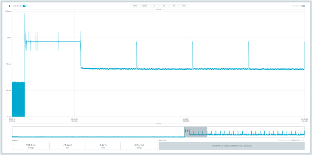
I tried to directly power the launchpad (all the jumpers except J8 were disconnected) with rectifier setup, somehow Vcc can only reach 1.58V and stuck there, (I guess this is because of the brown out reset)? By increasing the signal generator output power to 8dBm, and holding down reset button, launchpad can boot up and run normally. After boot up, even if signal generator power is reduced to 5dBm, launchpad can still operate.

Attached is launchpad's current consumption graph in boot up and running state (not sure it helps or not, we used nRF-PPK2 to capture the launchpad's current profile)
Questions:
1. Is there any specific power requirement during boot up? I checked the datasheet and there are a lot TBD :(
2. Is there any method to avoid boot up being held in 1.58V? There is a space constrain for our implant and we would like to use as less components as possible.
3. Not sure if should be asked here: when will XMSM0C1104SDSGR be released?

  • Hi Kit,

    The MSPM0 was designed to power up very quickly and for that reason, it is possible it can draw 2-3mA for the first 250usec.

    Regarding the POR, I'm not exactly sure what you are asking here.

    The MSPM0C1104SDSGR is sampling today. RTM in May.

  • Hi Dennis,

    Thank you for the reply.

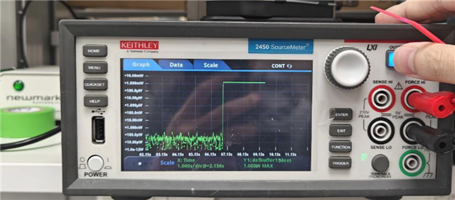
    Our RF + rectifier setup can only provide very little power (as I mentioned, several hundreds uW to 1-2 mW level. voltage will drop depending on load). Indeed, to make things easier, I used a source meter to generate some testing results without using rectifier.
    1: the output voltage is set to 3V with limiting current of 1mA: MCU boot up is failed, and continue to eat up 1.6 mW (Note that now voltage at 1.58V and current at 1mA).


    2. the output voltage is set to 3V with limiting current of 2mA: MCU will boot up. And after boot up since the chip is operating between RUN2STOP2 and STANDBY, power consumption is uW level (which our rectifier setup can cater). Now even putting lower value of current limit (down to ~500 uA), the chip can still operate.

    So I am wondering is there any suggestions to ease the need of boot up power consumption.

  • Unfortunately the system is designed to startup at full 32MHz and execute it's boot and configuration code very quickly before jumping to the application code.  It is possible to skip a portion of the boot code, but the CPU is still operating at full speed during this time and the current will still be high.

    Other customers with similar current limitations at startup have reported same problem. Our system and design team is fully aware and I'm being told that unlike our MSP430, which boot slower and and consume lower current, the MSPM0 was designed to provide a fast boot, thus the higher current.  It is a tradeoff. 

    One suggested option is to store a charge in a large cap, say a 100uF, during power up and use the charge to deliver the startup current to the MSPM0.  This is how one customer was able to make this work for them.  Unfortunately I don't have the details how they implemented this.

  • Hi Dennis,

    You are correct that adding capcitor could help. But when charging the cap, MCU I guess will still stuck at the state that eat up all the power, making capacitor unable to fully charge.

    It seems there are some voltage supervisor chips can be tweaked to cut the MCU power during capacitor charge. I will take a look first.

    Thank you,

    Kit

  • I assume you have some means of keeping the MCU off until the voltage builds up to a certain value. The point here is to keep the MCU off (or in reset) until the capacitor is charged.

    You might be able to do this with a judicious choice of the reset capacitor.

  • Hi Keith,

    You are correct that holding MCU in reset state will help.

    I did tried to put up a RC delay on NRST pin to hold the MCU at reset state, MCU booted up with delay (100kOhm & 0.47uF MLCC). However, it took very long to discharge the capacitor. This is not preferable in our use case because it means there will be a 'cool down' time between power cycles :(

  • Hi Kit,

    Have you made progress on this or do you still need help?

  • Hi Dennis,

    Problem solved by adjusting power setting from RF side. Thank you for your support!

**Attention** This is a public forum