Part Number: MSP430FR2355
Hello,
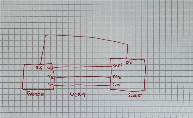
I would like to cummunicate between two MSP430FR2355 with a SPI communication. I have one master microcontroller, and five slave microcontrollers (all microcontroller are MSP430FR2355).
The Spi configuration of my master is in 3wire and I use 5 IO for Chip select the right slave. All the slave are in 4 wire configuration.
My problem is the following:
I can't send and receive any data when I use the mode_2 of slave spi (Chip Select Active low). But when I use the mode_1 (Chip Select Active High) I can send and receive data. My IO connect to the STE pin hold High at 1.6V, even I configure the IO low.
Is STE connected to IO possible with this type of microcontroller?
//SLAVE SPI

#include <msp430.h>
#include "gpio.h"
int main(void)
{
    WDTCTL = WDTPW|WDTHOLD;                   // Stop watchdog timer


    //Configuration SPI pins on Hardawre
    P4SEL0 |= BIT0 | BIT1 | BIT2 | BIT3;             // set 4-SPI pin as second function

    GPIO_setAsOutputPin(GPIO_PORT_P2, GPIO_PIN3); //indication alimentation
    GPIO_setOutputHighOnPin(GPIO_PORT_P2, GPIO_PIN3);

    GPIO_setAsOutputPin(GPIO_PORT_P2, GPIO_PIN4); //indication reception
    GPIO_setOutputLowOnPin(GPIO_PORT_P2, GPIO_PIN4);

    UCA1CTLW0 |= UCSWRST;                     // **Put state machine in reset**
    UCA1CTLW0 |= UCSYNC|UCMSB|UCMODE_1|UCSTEM;         // 3-pin, 8-bit SPI slave
                                              // Clock polarity high, MSB
    UCA1CTLW0 |= UCSSEL__SMCLK;                // ACLK
    UCA1BR0 = 0x02;                           // BRCLK = ACLK/2
    UCA1BR1 = 0;                              //

    UCA1CTLW0 &= ~UCSWRST;                    // **Initialize USCI state machine**

    PM5CTL0 &= ~LOCKLPM5;                     // Disable the GPIO power-on default high-impedance mode
                                              // to activate previously configured port settings
    UCA1IE |= UCRXIE;                     // Enable TX interrupt
    __bis_SR_register(GIE);       // Enter LPM0, enable interrupts
}

#pragma vector=USCI_A1_VECTOR
__interrupt void USCI_A1_ISR(void)
{   while (!(UCB1IFG&UCTXIFG));               // USCI_B1 TX buffer ready?
    UCA1TXBUF = UCA1RXBUF;                    // Echo received data
    GPIO_toggleOutputOnPin(GPIO_PORT_P2, GPIO_PIN4);
}
//MASTER SPI

#include <msp430.h>
#include "gpio.h"

/**
 * main.c
 */

//3.6 CS
//UCA1 SPI


unsigned char TXData;
unsigned char RXData;                            // Holds TX data

int main(void)
{
	WDTCTL = WDTPW | WDTHOLD;	// stop watchdog timer

    P4SEL0 |= BIT3 | BIT2 | BIT1;             // set 3-SPI pin as second function

    GPIO_setAsOutputPin(GPIO_PORT_P3, GPIO_PIN6);


    GPIO_setAsOutputPin(GPIO_PORT_P2, GPIO_PIN3);

    UCA1CTLW0 |= UCSWRST;                     // **Put state machine in reset**

    UCA1CTLW0 |= UCMST|UCSYNC|UCMSB;          // 3-pin, 8-bit SPI master
                                              // Clock polarity high, MSB
    UCA1CTLW0 |= UCSSEL__SMCLK;                // Select SMCLK

    UCA1BR0 = 0x02;                           // BRCLK = SMCLK/2
    UCA1BR1 = 0;                              //

    UCA1CTLW0 &= ~UCSWRST;                    // **Initialize USCI state machine**

    TXData = 0x01;                            // Holds TX data

    PM5CTL0 &= ~LOCKLPM5;

    GPIO_setOutputHighOnPin(GPIO_PORT_P2, GPIO_PIN3);
    //GPIO_setOutputHighOnPin(GPIO_PORT_P3, GPIO_PIN6);
    while(1)
    {
        UCA1IE |= UCTXIE;                     // Enable TX interrupt
        __bis_SR_register(GIE);   // enable global interrupts, enter LPM0
        __no_operation();                     // For debug,Remain in LPM0
        __delay_cycles(10000);                 // Delay before next transmission
        TXData++;                             // Increment transmit data
    }
}


#pragma vector=USCI_A1_VECTOR
__interrupt void USCI_A1_ISR(void)
{
    switch(__even_in_range(UCA1IV,USCI_SPI_UCTXIFG))
    {
        case USCI_NONE: break;                // Vector 0 - no interrupt
        case USCI_SPI_UCRXIFG:
              RXData = UCA1RXBUF;
              UCA1IFG &= ~UCRXIFG;
              break;
        case USCI_SPI_UCTXIFG:
            GPIO_setOutputLowOnPin(GPIO_PORT_P3, GPIO_PIN6);
              UCA1TXBUF = TXData;             // Transmit characters
            GPIO_setOutputHighOnPin(GPIO_PORT_P3, GPIO_PIN6);
              UCA1IE &= ~UCTXIE;
              break;
        default: break;
    }
}