


Other Parts Discussed in Thread: MSP-EXP430FR6989
Im using a MSP-EXP430FR6989 launchpad with BMI160 accelerometer(Booster sensor pack) to read accelerometer values from z-axis and also to put microcontroller to sleep whenever accelerometer is not moved.
Expectations:
I want to achieve current consumption of around or lower than 10 microAmpere during Low power/sleep mode. I want MSP430 to completely sleep and only wake up, whenever accelerometer is moved.
I have tried so far:
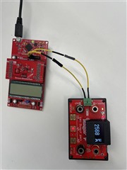
So far I have only achieved 2500 microAmpere in sleep mode, which is too much compared to expectations. I measured 2500 microAmpere by placing a ammeter on the 3.3V Pin in series of launchpad. Attached photo can be referred.
 Code which is used is:
 #include "driverlib.h"
#include <gpio.h>
#include <intrinsics.h>
#include <msp430fr5xx_6xxgeneric.h>
#include <stdint.h>
#include <stdio.h>
#include <msp430.h>
//Address if the BMI160
#define SLAVE_ADDR 0x69
//Maximum I2C buffer size
#define MAX_BUFFER_SIZE 20
#define BMI160_INT_PIN BIT2 // P3.2 is connected to the BMI160 interrupt pin (INT1)
//Number of FFT samples
#define SAMPLES 10
//#define TimeStampSample 10
#pragma PERSISTENT(input)
int16_t input[SAMPLES] = {0}; //Store samples
volatile uint32_t cycleCount;
#define UP 0x0010 // Timer_A Up mode
#define CONTINUOUS 0x0020 // Timer_A Continuous mode
#define ACLK 0x0100 // Timer_A SMCLK source
#define DEVELOPMENT 0x5A80 // Stop the watchdog timer
#define BOUNCE_DELAY 0xA000 // Delay for Button Bounce
#define MS_10 100 // Approximate value to count for 10ms
#define SMCLK 0x0200 // Timer_A SMCLK source
typedef enum I2C_ModeEnum{
IDLE_MODE,
NACK_MODE,
TX_REG_ADDRESS_MODE,
RX_REG_ADDRESS_MODE,
TX_DATA_MODE,
RX_DATA_MODE,
SWITCH_TO_RX_MODE,
SWITHC_TO_TX_MODE,
TIMEOUT_MODE
} I2C_Mode;
I2C_Mode MasterMode = IDLE_MODE;
uint8_t TransmitRegAddr = 0; //Register address for transmission
uint8_t ReceiveBuffer[MAX_BUFFER_SIZE] = {0}; //Buffer for received values
uint8_t RXByteCtr = 0; //Count received bytes
uint8_t ReceiveIndex = 0; //Index of received data
uint8_t TransmitBuffer[MAX_BUFFER_SIZE] = {0}; //Buffer for transmitted values
uint8_t TXByteCtr = 0; //Count transmitted bytes
uint8_t TransmitIndex = 0; //Index of transmitted data
volatile uint8_t exitLowPowerFlag = 0; // Global flag to indicate exit conditio
void initI2C()
{
UCB1CTLW0 = UCSWRST; // Enable SW reset
UCB1CTLW0 |= UCMODE_3 | UCMST | UCSSEL__SMCLK | UCSYNC; // I2C master mode, SMCLK
UCB1BRW = 160; // fSCL = ACLK/160 = ~100kHz
UCB1I2CSA = SLAVE_ADDR; // Slave Address
UCB1CTLW0 &= ~UCSWRST; // Clear SW reset, resume operation
UCB1IE |= UCNACKIE;
}
//******************************************************************************
// BMI160 Functions ************************************************************
//******************************************************************************
void bmi160_init(char FOC_axis)
{
uint8_t writeData[1];
//Read Chip ID, which is D1
I2C_Master_ReadReg(SLAVE_ADDR, 0x00, 1);
if(ReceiveBuffer[0] != 0xD1)
{
//UART_transmitString(" Incorrect sensor chip ID ");
printf("Incorrect sensor chip ID\n");
}
//Configure the accelerometer
writeData[0]=0b00101000; //Set acc_us to 0 for off, and acc_bwp must then be 010. Set acc_odr to 1011(800Hz),1100(1600Hz),1000(100Hz),0001(25/32Hz)
I2C_Master_WriteReg(SLAVE_ADDR, 0x40, writeData, 1);
//Check if configuration worked
I2C_Master_ReadReg(SLAVE_ADDR, 0x40, 1);
if(ReceiveBuffer[0] != writeData[0])
{
//UART_transmitString(" Accelerometer config failed ");
printf("Accelerometer config failed\n");
}
//Set the range of the accelerometer
writeData[0]=0b1000; //0b0011 for 2g, 0b0101 for 4g, 0b1000 for 8g
I2C_Master_WriteReg(SLAVE_ADDR, 0x41, writeData, 1);
//Check if range is set
I2C_Master_ReadReg(SLAVE_ADDR, 0x41, 1);
if(ReceiveBuffer[0] != writeData[0])
{
//UART_transmitString(" Accelerometer range set failed ");
printf("Accelerometer range set failed\n");
}
//Set the Accelerometer to normal power mode
writeData[0] = 0x11;
I2C_Master_WriteReg(SLAVE_ADDR, 0x7E, writeData, 1);
//Read power mode status of sensors
I2C_Master_ReadReg(SLAVE_ADDR, 0x03, 1);
if(ReceiveBuffer[0] != 0x10)
{
//UART_transmitString(" Accelerometer not on ");
printf("Accelerometer not on\n");
}
//GPT
// Configure any-motion interrupt
// Enable any-motion detection on all axes
writeData[0] = 0x14; // Enable any-motion on X, Y, Z axes
I2C_Master_WriteReg(SLAVE_ADDR, 0x60, writeData, 1);
// Set the any-motion threshold
writeData[0] = 0x14; // Threshold value (example)
I2C_Master_WriteReg(SLAVE_ADDR, 0x62, writeData, 1);
// Set the duration for any-motion detection
writeData[0] = 0x0A; // Duration value (example)
I2C_Master_WriteReg(SLAVE_ADDR, 0x63, writeData, 1);
// Map any-motion interrupt to INT1
writeData[0] = 0x04; // Map any-motion to INT1
I2C_Master_WriteReg(SLAVE_ADDR, 0x56, writeData, 1);
// Enable INT1 pin
writeData[0] = 0x08; // Enable INT1 output
I2C_Master_WriteReg(SLAVE_ADDR, 0x53, writeData, 1);
}
void initGPIO()
{
// I2C pins (P4.0 is SDA, P4.1 is SCL)
P4SEL1 |= BIT0 | BIT1;
P4SEL0 &= ~(BIT0 | BIT1);
P3DIR &= ~BMI160_INT_PIN; // Set as input
P3REN |= BMI160_INT_PIN; // Enable pull-up/down resistor
P3OUT |= BMI160_INT_PIN; // Set pull-up resistor
P3IES &= ~BMI160_INT_PIN; // Interrupt on low-to-high transition
P3IFG &= ~BMI160_INT_PIN; // Clear interrupt flag
P3IE |= BMI160_INT_PIN; // Enable interrupt
// Disable the GPIO power-on default high-impedance mode to activate
// previously configured port settings
PM5CTL0 &= ~LOCKLPM5;
//__bis_SR_register(GIE);
}
void CopyArray(uint8_t *source, uint8_t *dest, uint8_t count)
{
uint8_t copyIndex = 0;
for (copyIndex=0; copyIndex<count; copyIndex++)
{
dest[copyIndex]=source[copyIndex];
}
}
I2C_Mode I2C_Master_ReadReg(uint8_t dev_addr, uint8_t reg_addr, uint8_t count)
{
//printf("R\n");
/* Initialize state machine */
MasterMode = TX_REG_ADDRESS_MODE;
TransmitRegAddr = reg_addr;
RXByteCtr = count;
TXByteCtr = 0;
ReceiveIndex = 0;
TransmitIndex = 0;
/* Initialize slave address and interrupts */
UCB1I2CSA = dev_addr;
UCB1IFG &= ~(UCTXIFG + UCRXIFG); // Clear any pending interrupts
UCB1IE &= ~UCRXIE; // Disable RX interrupt
UCB1IE |= UCTXIE; // Enable TX interrupt
UCB1CTLW0 |= UCTR + UCTXSTT; // I2C TX, start condition
__bis_SR_register(CPUOFF+OSCOFF+SCG1+SCG0 + GIE); // Enter LPM4 w/ interrupts
// UCB1IE &= ~UCRXIE; // Disable RX interrupt
return MasterMode;
}
I2C_Mode I2C_Master_WriteReg(uint8_t dev_addr, uint8_t reg_addr, uint8_t *reg_data, uint8_t count)
{
/* Initialize state machine */
MasterMode = TX_REG_ADDRESS_MODE;
TransmitRegAddr = reg_addr;
//Copy register data to TransmitBuffer
CopyArray(reg_data, TransmitBuffer, count);
TXByteCtr = count;
RXByteCtr = 0;
ReceiveIndex = 0;
TransmitIndex = 0;
/* Initialize slave address and interrupts */
UCB1I2CSA = dev_addr;
UCB1IFG &= ~(UCTXIFG + UCRXIFG); // Clear any pending interrupts
UCB1IE &= ~UCRXIE; // Disable RX interrupt
UCB1IE |= UCTXIE; // Enable TX interrupt
UCB1CTLW0 |= UCTR + UCTXSTT; // I2C TX, start condition
__bis_SR_register(CPUOFF+OSCOFF+SCG1+SCG0 + GIE); // Enter LPM4 w/ interrupts
//printf("W\n");
return MasterMode;
}
void init_LowPowerMode(void)
{
printf("LPM4\n");
__bis_SR_register(CPUOFF+OSCOFF+SCG1+SCG0 + GIE); // Enter LPM4 with interrupts enabled
}
//I2C Interrupt
#pragma vector = USCI_B1_VECTOR
__interrupt void USCI_B1_ISR(void)
{
//Must read from UCB1RXBUF
uint8_t rx_val = 0;
switch(__even_in_range(UCB1IV, USCI_I2C_UCBIT9IFG))
{
case USCI_NONE: break; // Vector 0: No interrupts
case USCI_I2C_UCALIFG: break; // Vector 2: ALIFG
case USCI_I2C_UCNACKIFG: // Vector 4: NACKIFG
UCB1CTLW0 |= UCTXSTT; // Re-send start if NACK
break;
case USCI_I2C_UCSTTIFG: break; // Vector 6: STTIFG
case USCI_I2C_UCSTPIFG: break; // Vector 8: STPIFG
case USCI_I2C_UCRXIFG3: break; // Vector 10: RXIFG3
case USCI_I2C_UCTXIFG3: break; // Vector 12: TXIFG3
case USCI_I2C_UCRXIFG2: break; // Vector 14: RXIFG2
case USCI_I2C_UCTXIFG2: break; // Vector 16: TXIFG2
case USCI_I2C_UCRXIFG1: break; // Vector 18: RXIFG1
case USCI_I2C_UCTXIFG1: break; // Vector 20: TXIFG1
case USCI_I2C_UCRXIFG0: // Vector 22: RXIFG0
rx_val = UCB1RXBUF;
if (RXByteCtr)
{
ReceiveBuffer[ReceiveIndex++] = rx_val;
RXByteCtr--;
}
if (RXByteCtr == 1)
{
UCB1CTLW0 |= UCTXSTP;
}
else if (RXByteCtr == 0)
{
UCB1IE &= ~UCRXIE;
MasterMode = IDLE_MODE;
__bic_SR_register_on_exit(CPUOFF+OSCOFF+SCG1+SCG0); // Exit LPM0
//chatgpt
//__bic_SR_register_on_exit(LPM3_bits); // Exit LPM0
}
break;
case USCI_I2C_UCTXIFG0: // Vector 24: TXIFG0
switch (MasterMode)
{
case TX_REG_ADDRESS_MODE:
UCB1TXBUF = TransmitRegAddr;
if (RXByteCtr)
MasterMode = SWITCH_TO_RX_MODE; // Need to start receiving now
else
MasterMode = TX_DATA_MODE; // Continue to transmision with the data in Transmit Buffer
break;
case SWITCH_TO_RX_MODE:
UCB1IE |= UCRXIE; // Enable RX interrupt
UCB1IE &= ~UCTXIE; // Disable TX interrupt
UCB1CTLW0 &= ~UCTR; // Switch to receiver
MasterMode = RX_DATA_MODE; // State state is to receive data
UCB1CTLW0 |= UCTXSTT; // Send repeated start
if (RXByteCtr == 1)
{
//Must send stop since this is the N-1 byte
while((UCB1CTLW0 & UCTXSTT));
UCB1CTLW0 |= UCTXSTP; // Send stop condition
}
break;
case TX_DATA_MODE:
if (TXByteCtr)
{
UCB1TXBUF = TransmitBuffer[TransmitIndex++];
TXByteCtr--;
}
else
{
//Done with transmission
UCB1CTLW0 |= UCTXSTP; // Send stop condition
MasterMode = IDLE_MODE;
UCB1IE &= ~UCTXIE; // disable TX interrupt
__bic_SR_register_on_exit(CPUOFF+OSCOFF+SCG1+SCG0); // Exit LPM0
//chatgpt
//__bic_SR_register_on_exit(LPM3_bits); // Exit LPM0
}
break;
default:
__no_operation();
break;
}
break;
default: break;
}
}
//GPIO Interrupt Service Routine
#pragma vector=PORT3_VECTOR
__interrupt void Port_3(void)
{
printf("Any-motion detected1!\n");
if (P3IFG & BMI160_INT_PIN)
{
P3IFG &= ~BMI160_INT_PIN; // Clear interrupt flag
// Handle any-motion interrupt
__bic_SR_register_on_exit(CPUOFF+OSCOFF+SCG1+SCG0); // Exit LPM3
}
}
int main(void)
{
WDTCTL = WDTPW | WDTHOLD; // Stop watchdog timer
//WDTCTL = WDTPW; // Stop watchdog timer
//Initialize all peripherals
//initClockTo16MHz();
initGPIO();
//UART_init();
initI2C();
//timer_init();
bmi160_init('Z');
_BIS_SR(GIE);
int i=0;
// Activate all interrupts
init_LowPowerMode();
while(1)
{
printf("Reading samplesss\n");
//Read SAMPLES amount of data from the BMI160
for(i=0;i<SAMPLES;i++)
{
I2C_Master_ReadReg(SLAVE_ADDR, 0x16, 2); //Read the acceleration value from the BMI160 registers
input[i]= ReceiveBuffer[0] | (ReceiveBuffer[1] << 8); //Store the value in an array
printf("%d\n", (unsigned)(input[i]));
}
}

