This thread has been locked.

If you have a related question, please click the "Ask a related question" button in the top right corner. The newly created question will be automatically linked to this question.

Elapsed and Differential Time between 2 sources with Speed

Other Parts Discussed in Thread: MSP430F2274, CC2500

Our local Soap Box Derby track has a very old timing system that basically provides us with 3 digit precision (0.000 seconds) in regards to a heat winner and their lane (1 or 2).  We were discussing building a new timer system that would provide us elapsed time, average speed per sample point, and speed at each sample point along with the winner lane.  Ideally the new solution should run to 4 digit precision (0.0000 seconds) as we currently do get "ties".

My question is this:  Is the MSP430 launchpad with attached IR beams and encoded IR signals (to alleviate noise and cross-talk)  fast enough for something like this.  Doing the math the sample rates for Timer_A are high enough but that doesn't take into account the low bandwidth associated with IR transmission and/or encode/decode verification.

I'm really new to all of this and still doing a great deal of research (trying to find info on lossless schemes, elapsed time calculation, etc)...

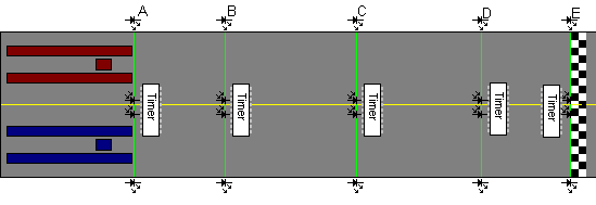
My basic concept was when a car passes through one of the beams start Timer_A and Timer_B.  When the 2nd car passes stop Timer_A when the tail of the car passes stop Timer_B.  Timer_A contains the differential time between lanes (IE: winner time) and Timer_B contains the speed of the winning lane with a small amount of math (see below psudo code).  Problem is that means I also need a Timer_C (and either I'm blind or it doesn't exist) to get the elapsed time of the other car breaking its beam.

The samples would then be sent to an RF Modem that would transmit it all back to a PC at the track that would do the final work building out speed profiles and keeping track of the bracket.

Any help, sample code, ideas on better ways (is IR really best or would cheap laser pointers and CDS cells be better) greatly appreciated.

PS: We aren't rich, or we would buy the multi-thousand dollar systems that do this for us :).  I will do my best to put all project details, schematics, source code, etc on the web for others to re-use though with credit where credit is due :)

 - Jeremy


function calculateSpeed(ellapsedSeconds, carLength){

  // borrowed and simplified from http://www.csgnetwork.com/csgtsd.html javascript source

  var distunitsvalue =  0.3048,    // Used for length of car in Feet

      speedunitsvalue = 0.44704; // Used for MPH calculation

  return ((carLength * distunitsvalue)  / (ellapsedSeconds * speedunitsvalue)); 

}

  • Hmm, the 2122 and 2131 included with the LaunchPad only have one single TimerA2, no TimerB. The MSP430G2xx3 parts have two TimerA modules. And with three CCR units each. So you'd have to get one of them in addition to the LaunchPad if you need two timers.

    Also, if you can manage to decode the IR signal outisde the MSP and just forward a trigger signal for each sample point and lane (up to 6 parallel for the 6 CCR units you have), you can use the hardware to detect the timing with even much higher precision than you pictured.

    The CCR units can 'capture' the current tiemr count when an external trigger signal arrives.

    So if you set up the timer to count with 1MHz, you will get a 1µs (6 digit) precision. So let's say the timer is reset on start and counts with 1Mhz (this is easiest). When the trigger is pulled for CCR1, it will capture the current timer count and trigger an interrupt. The software can now read the captured value, add the number of timer overflows which have occurred since start (happens after 65536 timer ticks) and you know the elapsed time since start in microseconds. When the trigger is pulled next (for the next sample point of the same track), the funciton repeats. As long as every track has its own trigger assigned for all of its sample points, and the points are triggering in the proper order (which should be the case), you can get lap times, total time and intermediate times.

    For the current speed, things are a bit more complicated. The front/rear measuring requires to know the exact length of the car. Hoever, you can set up the trigger to trigger on high- and low-going edge of the trigger, so it is not too much work. The time is long enough to process everything. Since the value ha sbeen captured, you have time until the next trigger on the same CCR unit before the exact moment info would be lost.

    Clocking the timer with a lower speed (e.g. 10kHz for 4 digits resolution) is a bit difficult as you cannot define a decimal divider for the timer clock signal. So you will have a binary divider and the math for converting it back into 1/1000s is a bit more complex. That's why 1MHz is the best choice.

    About the tranmission delay: as long as it it deterministice (always the same), it doesn't matter. Who cares whether you see the result some milliseconds later than when it really happened? As long as the relative timing is precise, nobody can complain (and nobody will notice anyway).

    But what about placing an MSP directly at each sample point? Yo don't need any IR transmission then and can directly use the signal form the IR sensor as trigger, calculate the information (speed etc.) and then send it using I2C or SPI to the central unit that does the display. If you synchronize the MSPs to the start signal (that's the difficult part then), then you will have no trouble with any transmission timing.


    In any case, you should not use any float math and not divisions in the code, as these are sloooooow. Use long integers for the counting/calculating, and when you need a division, check first if you cannot replace it by a multiplication and a shift. (shifts are *2^x or /2^x operations and ultra-fast). It really pays to do the additional math before writing the code.
    A long int can display ~35 minutes with microseconds resolution. So there really is no need to use floats.

  • Thanks greatly for your reply, it helps me to get going in the right direction.  I ordered some samples of the 2553 when I first started looking at this project (due in any day now) as it appears to be the largest chip in the G lineup.  My basic idea is if I start big I can always scale the chip as I know my final requirements.

    My current plan is to have a separate Launchpad at each sample location with the RTC installed on each to keep everything (hopefully) in a similar time set thus keeping everything in sync.  The IR will be sent from the outside of the track to the MSP and the receivers on the inside of the track something similar to the image below (not to scale at all, had to do some resizing to get it to even display here on the forums):

    I was thinking RF between A->E where when A gets started it will send some type of wakeup to the other nodes thus they will have plenty of time to initialize.  Basically we don't want to have to run a wire down the middle or across the track.  The wakup call I would think would carry some type of time sync, each line would have its own signature (A top and A bottom would be different and different from B top/bottom, etc) to lower cross talk.  Any time the lines are broken the timer will record how long each is broke and the delta between the breaks, then send that data back to the host PC via some link (our hopes are wireless, only time and cost will tell).

    I've looked at the $7 BlueTooth modules from DX but came to the realization that the range is just too limited at this point (only 5 meters).  Total length of the track is about 1000ft with the PC Host at one end or the other.  Back to the drawing board on wireless for now.

    The delay I was more worried about was the signature so I could tell A Top to A bottom to B Top to B Bottom etc...  Again trying to make sure that there isn't interference from the outside world as this will all be outside.  Most of the time we race during the day, but we do have some night races too.  People with laser pointers, flashlights, headlights, etc shouldn't cause bad readings.  To take out things like leafs crossing the track samples < a given rate will be discarded (we know the cars travel at a top speed of 35mph and are at least 6ft long, so if we see something moving at +45mph we know it isn't a car :))

    The cars are all the same size (given 1/4in tolerance)  within a given class, so calculation of speed should be easy enough.  Its just the details of setting up the timers, some type of IR encoding to assure proper measurements, and communications that has me going in circles.  I'd love to find a "for dummies" tutorial about setting up timers for something similar and one about lossless light encoding.  Any ideas?  I've searched but it seems the Launchpad is just too new or not utilized in this realm.  I've seen some code around PIC's and Pinewood but that doesn't quite scale well.

  • Quick additional note, I was thinking for the outside transmitters using a xtal osc hooked up to a shift register and a latch to act like a ring counter, thus repeating the pattern over and over at a known freq.  That way its cheap and easy to place/replace between rallies.  I may be overthinking this things though :)

  • For RTC synchronization, you can use the same way you're sendign the data.
    You're right, BT surely isn't suited.

    What about the RF2500 devices? I got some sets, but except of staring at them for a minute, I didn't use them yet, so I don't know whether they are suited. But you don't need too much hardware for the individual stations. YOu don't even need an RTC - if you get them synchronized right before the race, or by A (just a 'start your timers' pulse that is received by all of them synchronously), then a simple pulse-counting by the timer will be sufficient to keep them in sync for a few minutes.
    Of course, if you start them by passing A, you'll need to measure thr latency of the other nodes and hardcode it into the calculations

    However, the nodes don't even need to know the car size. It's enough that they all send their on/off time to the access point, which then can calculate it by the data passed to it, e.g. by a terminal.

    The RF2500 target board has an MSP430F2274 and a 2.4GHz transceiver and is listed for $20. The development kit with the USB-based programmer and two target boards comes for $49. If the transmission distance of the RF2500 is long enough (I assume open field conditions), this could be much cheaper than a combination of LaunchPad and an external RF transceiver.
    The 2274 has 32k Flash and 1k Ram, two timers and an USCI module. But I don' tknow whether the USCI module insn't alkready used for ommunicationg with the CC2500 RF chip. If so, you still have I2C or SPI for attaching an IR detector/decode chip. It even has a 10 bit ADC. for directly reading a sensor analog value (but then, for high precision and high speed, you should go for an external detector that just gives a high/low signal)


  • I had noticed the RF2500 devices but hadn't spent enough time looking at them to figure out exactly what I would need.  My guess would be 1 starter kit and 4 more target boards since it is nice to have extras when one gets broke.

    My thought on the Launchpads was the price to replace them was low, the RF2500's seem a bit more steep.  This is where I am glad I have all winter to play with different configurations and costs :).

    I agree with your statement of all the calculations happening back at the laptop, it keeps the solution a lot more simple.  As I really see only 3 numbers going back (Time A top broke, Time A bottom broke, Delta between A top and bottom) I could probably do it in one single packet.

    Looking at other projects that do exist on the net I thought of using the RFM12B radio module.  Seems that the difference is this:

    LaunchPad + RFM = $12 per unit, low freq (915Mhz), shorter range, cheaper, some assembly required

    RF2500 Target Board = $20 per unit, high freq (2.4Ghz), longer range, Prebuilt solution, sensor wires, program and go

    Time to order a few 2500's to play with and some RFM12B's to see what the difference actually ends up being between the two.  We have a police helicopter launchpad (literally) at the end of our track, so their interference will be taken into consideration as well.

    Thanks for all the help so far everyone... Though, I'm still confused how I perform two (3?) samples on the timer from two different triggers on the rising and falling (I hope I got that right) edges.  Tutorial still wanted :)

    - Jeremy

  • Jeremy Darling said:
    (Time A top broke, Time A bottom broke, Delta between A top and bottom)

    I think, the PC can calculate the delta by itself too, so only two values. :)
    Or 4, since one MSP can likely handle the signals for both tracks, if it is in the middle of them

    Jeremy Darling said:
    hough, I'm still confused how I perform two (3?) samples on the timer from two different triggers on the rising and falling (I hope I got that right) edges.

    The capture unit can trigger on rising or falling edge or both of one single signal source.

    However, every timer has more than one CCR unit, and each of them can handle a different signal. The 2274, that is in the EZ2500, has two timers, one of type TimerA, one of type TimerB (which doesn't make a difference for your application), and each of them has three CCR units.

    What basically happens: the timer continuously counts. it counts form 0 to 65535 and begins again from 0.
    If a CCR unit is configured for capture, and the configured edge is detected, it captures the current content of TimerA into its data register and triggers an interrupt. Until the next event happens, you can read the data register and get the timer count at the moment of the event.

    To get the distance between two evety, you'll just need to get the two captured values and subtract them and you have the timer difference in timer ticks (which translates to a time value if you know the timer tick rate, which you should :) )
    This works for any time delay that is smaller than one timer round (65536 ticks). If your delay is larger (whcih is is in your case), you need to also count the timer overflows and save the current overflow count together with the captured value. (you can just combine the two into a long int before doing the math).

    It can be a bit tricky to ensure that you detect overflows and captures in the right order. (something like: if you see an overflow and a capture at the same time and the capture is only a small nmumber, then it belongs to the current TAR cycle, if the capture is a large number, then it belongs to the last cycle and the overflow occurred after it)

    As usual, there is more than one way to do things. The exact approach depends on the project details: what timings are to expect (worst/best case), processor speed (which influences power consumption), etc.

    BTW: the G series devices do not have calibrated DCO frequencies, teh 2274 has calibration values for 1,8,12 and 16MHz operation. And you'll need a rather accurate timebase for your timings. So teh LaunchPad wouldn't be really suited, at least not without an individual calibration procedure to find the correct DCO settings for the desired frequency (which differ for each individual chip).

  • Reading through the data sheets on the Launchpad (I haven't got the RF2500's in or looked at their data sheets yet) it seems I would have to use P1.1 and P1.2 as my two inputs from my CDS cells (most likely buffered through a simple 2n2222 since this is a Digital input).  Also, reading http://lambentresearch.com/embedded.html it would seem I can keep the DCO calibrated using the external RTC that ships with the kit (would just have to solder it in place) and then calibrating every n cycles.

    But I also noted where TXD and RXD are also placed on these pins, so that seems to remove my ability to use the internal UART for serial communications :(, then maybe I should use the I2C bus for communications?

    Knowing that you can only clock the internal OSC to 1, 2, 8 and 16 would an external xtal at 10Mhz make more sense?  If so, then do I need the RTC at all as I will have a known speed (within tolerance).

    I've also started reading the tutorials at http://mspsci.blogspot.com in hopes that they explain some of the details I'm lacking knowledge in with regards to interrupts and timers.

    So far, here is what I have come up with:

      1) When the gate drops send a signal out to all the systems telling them to reset to 0.

      2) Wake up when we get this signal

          a) calibrate the DCO (unless using an external xtal)

          b) clear overflow counter

          c) clear start and end time values associated with p1.1 and p1.2

      3) Wait for a transition on 1.1 or 1.2

      4) on a (positive or start) transition

          a) record overflow count and timer value to some start variables

      5) on a (negative or stop) transition

          a) record overload count and timer value to some end variables

          b) check if we have 4 total samples (two starts and two stops), if so send back the samples to the PC or analysis

      6) once we have all samples and have transmitted the values go back to sleep and wait for next wakeup signal

    Edge cases that need to be taken into consideration:

      1) If the sample end-start is lower than some value then we need to throw it away, could have been a leaf or something on the track

      2) If we get a start signal but after a threashold we don't have a stop signal (say 5 seconds) then send an error saying something is wrong

      3) If we get two starts on the same channel without a stop send an error, we have something wrong (should never happen, but who knows)

      4) Same as 3 except with ends

    This makes it seem that psudo code for the above may look as follows:

      void main(){

        // yeah... haven't quite figured out what this should do yet

        setupTimersAndInterrupts();

      }

      long ticsToLong(int overflows){

        return TACCR0+(overflows*65535);

      }

      void onP1_1rise(){

        if(lane1Start>0) uart_write('Error: two starts on lane 1');

        lane1Start = ticsToLong(overflows);

      }

      void onP1_2rise(){

        if(lane2Start>0) uart_write('Error: two starts on lane 2');

        lane2Start = ticsToLong(overflows);

      }

      void onP1_1fall(){

        if(lane1End>0) uart_write('Error: two ends on lane 2');

        if(lane1End-lane2Start<5000){

          // sample too short, car would be doing like 100Mph

          lane1Start=0;

          lane1End  =0;

        }else{

          lane1End = ticsToLong(overflows);

          checkSendValues();

        }

      }

      void onP1_2fall(){

        if(lane2End>0) uart_write('Error: two ends on lane 2');

        if(lane2End-lane2Start<5000){

          // sample too short, car would be doing like 100Mph

          lane2Start=0;

          lane2End  =0;

        }else{

          lane2End = ticsToLong(overflows);

          checkSendValues();

        }

      }

      void checkSendValues(){

        if(lane1End&&lane2End){

          uart_write('RaceEnd:', lane1Start, lane1End, lane2Start, lane2End);

        }

      }

      void startRace(){

        lane1Start=0;

        lane2Start=0;

        lane1End  =0;

        lane2End  =0;

        overflows =0;

      }

    I am leaning toward the RF2500 and even noted where it can be used in conjunction with the Launchpad as a programmer according to the docs.  Just have to wait till I have the extra $$ lying around to pick a few up to play with.

    Sorry for all the posts and questions regarding this, but before I got off into the wild and start trying to build something I want to make sure I have the concepts sound in my mind :).

     - Jeremy

**Attention** This is a public forum