This thread has been locked.

If you have a related question, please click the "Ask a related question" button in the top right corner. The newly created question will be automatically linked to this question.

MSP430FR6047: How to R/W with spi flash (w25q40) in msp430fr6047

Part Number: MSP430FR6047
Other Parts Discussed in Thread: UNIFLASH

Tool/software:

hello
We are working on a project to develop a water meter with msp430fr6047.
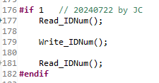
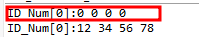
I'm trying to use SPI flash (w25q40) to input user-defined variables.
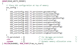
The code used for development is UltrasonicWaterFR604x_02_40_00_00. Are there any examples or references that match the code?
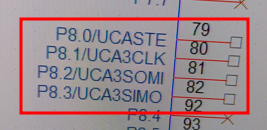
The spi flash connection port is as follows.

I need help.
thank you

  • Sorry, we don't have such code. I think the easy way is to find a code based on w25q40 + other MCUs. And migrate it to MSP430 based on SPI code example.

  • Thank you for your reply.


    If you do not use an external spi flash such as w25q, is there an area of ​​about 128 bytes in the non-volatile memory space inside the msp430fr6047 that can store user-defined environment variables in addition to the area used for operation?
    If so, I would like to find a Read/Write method for that area.

  • Yes, FRAM can be erase and write in Byte. You can refer to the code example and choose any address as EEPROM. The suggest range is the last 128 byte. For the available range, you can refer to the .cmd file.

  • Thank you for your reply.

    I'm curious where I can find the FRAM Access example you mentioned.

    For your information, I would like to use it to enter custom information such as the equipment identification number of an ultrasonic meter, but I am curious as to whether this area can be erased with a FW programmer such as UNIFLASH.
    Will the area where I put my custom information be erased?
    Even if I udate FW with FW programmer, it should not be erased. Is this possible?

  • Here is the code example:

    msp430fr60x7_framwrite.c
    /* --COPYRIGHT--,BSD_EX
     * Copyright (c) 2016, Texas Instruments Incorporated
     * All rights reserved.
     *
     * Redistribution and use in source and binary forms, with or without
     * modification, are permitted provided that the following conditions
     * are met:
     *
     * *  Redistributions of source code must retain the above copyright
     *    notice, this list of conditions and the following disclaimer.
     *
     * *  Redistributions in binary form must reproduce the above copyright
     *    notice, this list of conditions and the following disclaimer in the
     *    documentation and/or other materials provided with the distribution.
     *
     * *  Neither the name of Texas Instruments Incorporated nor the names of
     *    its contributors may be used to endorse or promote products derived
     *    from this software without specific prior written permission.
     *
     * THIS SOFTWARE IS PROVIDED BY THE COPYRIGHT HOLDERS AND CONTRIBUTORS "AS IS"
     * AND ANY EXPRESS OR IMPLIED WARRANTIES, INCLUDING, BUT NOT LIMITED TO,
     * THE IMPLIED WARRANTIES OF MERCHANTABILITY AND FITNESS FOR A PARTICULAR
     * PURPOSE ARE DISCLAIMED. IN NO EVENT SHALL THE COPYRIGHT OWNER OR
     * CONTRIBUTORS BE LIABLE FOR ANY DIRECT, INDIRECT, INCIDENTAL, SPECIAL,
     * EXEMPLARY, OR CONSEQUENTIAL DAMAGES (INCLUDING, BUT NOT LIMITED TO,
     * PROCUREMENT OF SUBSTITUTE GOODS OR SERVICES; LOSS OF USE, DATA, OR PROFITS;
     * OR BUSINESS INTERRUPTION) HOWEVER CAUSED AND ON ANY THEORY OF LIABILITY,
     * WHETHER IN CONTRACT, STRICT LIABILITY, OR TORT (INCLUDING NEGLIGENCE OR
     * OTHERWISE) ARISING IN ANY WAY OUT OF THE USE OF THIS SOFTWARE,
     * EVEN IF ADVISED OF THE POSSIBILITY OF SUCH DAMAGE.
     *
     *******************************************************************************
     *
     *                       MSP430 CODE EXAMPLE DISCLAIMER
     *
     * MSP430 code examples are self-contained low-level programs that typically
     * demonstrate a single peripheral function or device feature in a highly
     * concise manner. For this the code may rely on the device's power-on default
     * register values and settings such as the clock configuration and care must
     * be taken when combining code from several examples to avoid potential side
     * effects. Also see www.ti.com/grace for a GUI- and www.ti.com/msp430ware
     * for an API functional library-approach to peripheral configuration.
     *
     * --/COPYRIGHT--*/
    //******************************************************************************
    //   MSP430FR60xx Demo - Long word writes to FRAM
    //
    //   Description: Use long word write to write to 512 byte blocks of FRAM.
    //   Toggle LED after every 100 writes.
    //   NOTE: Running this example for extended periods will impact the FRAM
    //   endurance. MPU is also enabled by default in CCS.
    //   MCLK = SMCLK = default DCO
    //
    //           MSP430FR6047
    //         ---------------
    //     /|\|               |
    //      | |               |
    //      --|RST            |
    //        |               |
    //        |               |
    //        |          P1.0 |---> LED
    //
    //   Evan Wakefield
    //   Texas Instruments Inc.
    //   October 2016
    //   Built with IAR Embedded Workbench V6.50 & Code Composer Studio V6.2
    //******************************************************************************
    #include <msp430.h>
    
    #define WRITE_SIZE      128
    
    void FRAMWrite(void);
    
    unsigned char count = 0;
    unsigned long data;
    
    #if defined(__TI_COMPILER_VERSION__)
    #pragma PERSISTENT(FRAM_write)
    unsigned long FRAM_write[WRITE_SIZE] = {0};
    #elif defined(__IAR_SYSTEMS_ICC__)
    __persistent unsigned long FRAM_write[WRITE_SIZE] = {0};
    #elif defined(__GNUC__)
    unsigned long __attribute__((persistent)) FRAM_write[WRITE_SIZE] = {0};
    #else
    #error Compiler not supported!
    #endif
    
    int main(void)
    {
        WDTCTL = WDTPW | WDTHOLD;               // Stop WDT
    
        // Configure GPIO
        P1OUT &= ~BIT0;                         // Clear P1.0 output latch for a defined power-on state
        P1DIR |= BIT0;                          // Set P1.0 to output direction
    
        // Disable the GPIO power-on default high-impedance mode to activate
        // previously configured port settings
        PM5CTL0 &= ~LOCKLPM5;
    
        // Initialize dummy data
        data = 0x00010001;
    
        while(1)
        {
            data += 0x00010001;
            FRAMWrite();
            count++;
            if (count > 100)
            {
                P1OUT ^= 0x01;                  // Toggle LED to show 512K bytes
                count = 0;                      // ..have been written
                data = 0x00010001;
            }
        }
    }
    
    void FRAMWrite(void)
    {
        unsigned int i = 0;
    
        for (i = 0; i < 128; i++)
        {
            FRAM_write[i] = data;
        }
    }
    

    For Uniflash, you can try this setting:

  • Thank you for your reply.

    I am curious to which address exactly the location of FRAM_write is connected to in the code above.
    Also, I have one more question, so I would like to inquire further.
    After checking lnk_msp430fr6047.cmd, JTAGSIGNATURE, BSLSIGNATURE, and IPESIGNATURE are set, but I could not find where they are used in the code.

    Is it okay if I change the locations corresponding to JTAGSIGNATURE, BSLSIGNATURE, and IPESIGNATURE for my own use using the code you answered?
    I would like to inquire because I am curious about the purpose of JTAGSIGNATURE, BSLSIGNATURE, and IPESIGNATURE.

    thank you

  • Writing to an SPI memory device is not particularly difficult. Consult the data sheet for the device in question for details. With luck you can turn up code on the Internet that you can adapt.

    As for using FRAM...

    The SIGNATURE values are used to lock those sorts of access and are not available as general storage. They are best left alone unless you know what you are doing.

    Even if you set an option to tell Uniflash to not erase everything, it only takes one mistake to erase it all. Or an errant pointer within your code. For critical data that must persist through a firmware update, use the SPI memory.

  • Thank you for answer.

    Our development project is to create a new ultrasonic meter based on the EVM430FR6047.
    So, I am using the base code as UltrasonicWaterFR604x_02_40_00_00. In addition, the ezFET part is omitted from the newly created ultrasonic meter, and it is made with a structure that operates with an external JTAG during FW programming.
    The ultrasonic meter you are planning to make has a 15mm measuring tube fixedly connected to it. Additionally, a unique 4-byte serial number must be entered into each ultrasonic meter to identify the ultrasonic meter.

    So, we asked about the need for the ability to read and write product numbers through FRAM or SPI Flash.


    Among them, as a result of checking the code, I could not find the source code (UltrasonicWaterFR604x_02_40_00_00) or any mention of JTAGSIGNATURE, BSLSIGNATURE, and IPESIGNATURE, which are included in the FRAM area, so I inquired.

    Only 4 bytes are needed for the product number.

    If the IPE SIGNATURE is an area that displays PIPE information or the BSL signature is displayed the EVM430Fr6047 board information,

    it seems to be usable as long as it is not used in UNIFLASH or USS GUI.

    I would like to ask again if there is any information about this.

    As a result of checking with the memory browser, the JTAGSIGNATURE, BSLSIGNATURE, and IPESIGNATURE areas are all filled with 0xFF as shown below.


    but, I can't find any examples related to spi flash...

    thank you

  • I don't suggest you to touch the signature part. For the description, you can find them in the UG.

    For how to make spi flash work, it is beyond our support range.  Is there any problem for you to save the data in FRAM?

  • Thank you for your reply.

    In the original code, VERSION was using 8 bytes, but it has been modified.

    Currently, it is being modified to use only 4 bytes for VERSION and 4 bytes for ID_NUM.

    I checked Write_IDNum() / Read_IDNum() without using #progma persistent, but it was reset to 0 when I turned the power off and on again and operated in CCS debug mode.

    Currently, I am trying to save it using the ID_Num area, but it is not saved, so I am editing it again.

    After adding #progma persistent, an error occurs as shown below.
    "../main.c", line 113 (col. 9): error #1521: variable "ID_Num" cannot be persistent and also have DATA_SECTION pragma. Without DATA_SECTION pragma, "ID_Num" will be in section .TI.persistent:ID_Num. With only DATA_SECTION pragma, you must mark the section persistent in the linker cmd file.
    "../main.c", line 113 (col. 9): warning #1519-D: variable "ID_Num" was declared persistent and should be explicitly initialized

    The test is being conducted in the debug mode of CCS, and to check the ID_Num saved value, the power is turned off and on again, and the memory is being checked after entering debug mode.

    How do I modify it to read the previously saved value the same even if the power is turned off and then back on?

  • After modifying as shown below, if you check by turning off and on the power of the EVM430fr6047, the value of Read_IDNum() that you try initially returns to 0.

    What should I do to keep the saved value even if I turn the power off and on after writing FRAM?

  • 1) Each time you download new code, Persistent (indeed everything but NOINIT) variables are re-initialized. (Watch out for the CCS download/erase options.)

    2) I'm a little unclear on your test sequence, but generally if you power-cycle the target (MCU) the debugger disconnects, and when (re-)connecting the debugger the code gets downloaded again. (It is possible to re-connect the debugger without re-loading the code, but as I recall (it's been a few years) it's a somewhat arcane procedure, and I don't see an indication that you're doing this.)

    3) I'm not sure what the compiler/linker does with the combination of PERSISTENT and LOCATION, since PERSISTENT is equivalent to DATA_SECTION(".TI.persistent") and that section goes down at 0x4000. My guess is that one (or both) is being ignored. Your Debug/<project>.map file should tell you something. Did you get any warnings?

    4) Is ID_Num's location important? The MPU (to enable writing to FRAM) has a 1KB granularity (which is why the RW section is PALIGN(0x400)) so you'll be write-enabling all ID_Num's neighbors. There's also the option of (temporarily) turning off/on the MPU entirely, which has its hazards but as I recall is fairly simple/quick.

    5) How did you plan to update ID_Num? (a) Within your application? or  (b) Using an external tool? I vaguely recall Elprotronics' software has a serial-numbering scheme which maybe could be pressed into service.

  • Only 4 bytes are needed for the product number.

    If a number unique to the device is required, you might want to look at the TLV data. Some of which is unique to each device.

  • Thank you for your reply.

    I didn't expect that memory would be initialized when reconnected in CCS debug mode.

    When the development of the ultrasonic meter we are making is almost complete, we plan to save the ID of each meter with a command through a separate debug uart.
    In other words, you can think of it as input and storage through debug uart using ultrasonic meter FW.


    In addition, since ultrasonic meters operate on batteries, even if the power is turned off and then turned on again, the stored individual meter ID will continue to be read so that the meter can be identified.

    The location of ID_Num (the ID of each meter) is not important.
    I proceeded with it because it seemed like it would be easier to identify and debug if it was in a fixed location on the FRAM.

    Currently, there is no newly created ultrasonic meter board yet, so we are only checking FRAM storage and reading with EVM640fr6047.

    After saving ID_Num consisting of 4 bytes in FRAM, I would like to check the code that can read the saved ID_Num even when reset and power off/on.


    In CCS debug mode, is there a way to read the ID_Num stored in FRAM as the previously entered value without initializing it?

  • I understand what you said.
    I got a hint from the below part of the cmd file.


    thank you

  • It sounds like you want:

    1) Updated almost-never; other times should be write-protected

    2) Updated using your own code

    3) It would be Very Nice if it didn't move around

    Information FRAM is tailor-made for this sort of thing, but the FR60xx series doesn't have that.

    The solutions I see (increasing complexity):

    A) Go back to your DATA_SECTION(".id_num") solution, but remove the PERSISTENT specification. Then in your Write function, bracket the assignment with something like [I don't own an FR6047 to try this on, but I'm pretty sure it will work]:

    MPUCTL0 = MPUPW | (0*MPUENA);  // Turn off the MPU -> no write protection (anywhere)
    ID_Num = new_value;  // (loop elided for brevity)
    MPUCTL0 = MPUPW | (1*MPUENA);  // Turn on the MPU

    B) Option (A) will (still) re-load the initial value each time you load new code. To prevent this, in the linker .cmd line that says ">ID_NUM", append "type = NOLOAD" ["type=NOINIT" may also work]. Then in "Project->Properties->Debug->MSP430 Flash Settings->Erase Options" choose "Erase and download necessary segments only".

    The hazard here is that after the (first) code download you don't know what's in there. A checksum might be useful. (Or maybe you don't care very much about this.)

    C) As a general thing, I actually agree with David Schultz: The least hazardous method is an external EEPROM/FLASH/FRAM, but yes it "costs" extra, and maybe (A) or (B) is enough.

**Attention** This is a public forum