This thread has been locked.

If you have a related question, please click the "Ask a related question" button in the top right corner. The newly created question will be automatically linked to this question.

Timer Interrupt MSP430


Hi,

I wrote following code. I set 0.5 sec timer in up mode in timer_a function. & then send it in LMP0 mode. Now instead of counting upto TACCR0 value, then go into ISR, CPU after entering LPM0 mode at once enters into ISR. I don't understand why.

Kindly help.

void timer_a(void)
{
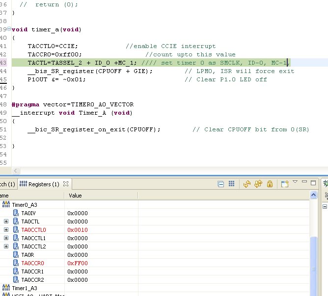
  TACCTL0=CCIE;            //enable CCIE interrupt
   TACCR0=0xff00;                //count upto this value
   TACTL=TASSEL_2 + ID_0 +MC_1; //// set timer 0 as SMCLK, ID-8, MC-2,taie-1
   __bis_SR_register(CPUOFF + GIE);        // LPM0, ADC10_ISR will force exit                           (LPM0 MODE)

   P1OUT=0x00;
}

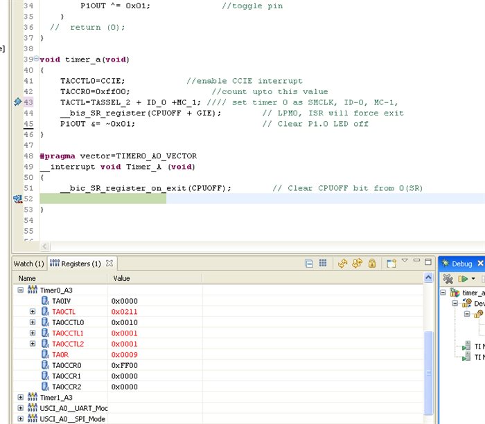
#pragma vector=TIMER0_A0_VECTOR
__interrupt void Timer_A (void)
{

 __bic_SR_register_on_exit(CPUOFF);        // Clear CPUOFF bit from 0(SR)
}


Regards

Deepak Bansal

  • Hi,


    I dont see why it should not work. When you set a breakpoint in the ISR is the TAR value 0xFF00?

    At what frequency runs your SMCLK? After your Example it should run at 130560 Hz???


  • When the compiler encounters // in your code, it ignores the rest of the line.

    The good news is, ADC10_ISR does not exist and will not force an exit of LPM0.

    The bad news is, the timer clock divider is 1, not 8. The Timer is running at SMCLK rate, not at SMCLK/8.

  • Daniel,

    I put breakpoint on line 43, & following was reading of my register with SMCLk= 1MHZ


    And after that I put breakpoint in line 52, & following was the values:


    And you said after my example SMCLK will run at 130560 HZ. Why is it so?


    Regards

    Deepak Bansal


  • old_cow_yellow


    Actually I changed lots of things in code while debugging & forget to change comments. Anyways, regrets for the mistake


  • According to the code at line #43, TimerA is counting at SMCLK/1 = 1MHz. It takes 0.065281 seconds for it to count from 0 to 0xFF00 (decimal 65280).

    According to the comments at line #43, the divider should be 8 instead of 1, and the delay would be 0.065281*8 = 0.587529 seconds.

    Unfortunately, you changed the comment, not the code.

  • Hi,

    Generating delay is not any issue. My question is after code at line #43, it should go in LPM0 mode, then will exit it when TACCR0 counts upto 0xff00 & from ISR it exits from LPM0 mode. But this is not happening in my case.Can't understand why?

  • Actually, the CUP goes to LPM0 with GIE after line #44 is executed.

    If you turned on the LED at P1.0 before LPM0, the LED will stay on. After the delay, the ISR will make the CPU exit LPM0 and line #45 will turn the LED off.

    Your original post says the delay should be 0.5 second. In that case the LED will be visible. But actually it is on for only 1/16 of a second and you probably cannot see it.

    The debugger is full of bugs. Do not depend on the debugger.

  • Hi, note that the debugger does not show you the time the MCU stays in LPM modes. LPM modes means that the clock sources as switched off. The debugger is using the clock sources for debugging. If the clock source is switched off you will not see anything in the debugger. Only if clock source is on you will see something on the debugger.

    So in LPM0 the CPU clock is off. If the MCU goes to LPM0 mode you will not see anymore that the debugger shows the number of clock cycles of timer module. As soon as the CPU wakes up you will get further details about the MCU via the debugger. This means, as soon as the Timer_A interrupt was generated the CPU wakes up and the debugger synchronizes again and you see the register contents. In your case the TA0R register content (this is the actual counter value) is 0x0009 when the breakpoint is set in the ISR. Well, you use Timer_A in up mode. This means it counts up to 0x0FF0 and then generates the interrupt. It takes 6 cycles to jump into the ISR (interrupt latency) and then the intrinsic function (_bic_SR_register_on_exit) is executed. Because SMCLK and MCLK seems to be identical some clock counts are added to the TA0R register. So the 0x0009 seems to be correct....

    If you want to measure the time the controller stays in LPM0 mode then I would add a test output signal. For example you could configure a Port Pin (e.g. P1.0) as a digital output. As soon as you start the counter you can set the port output and as soon as the code enters the ISR you could clear the port output. Then it is quite simple to measure the time with an oscilloscope.

  • Many thanks, Voyager for reply.


    Regards

    Deepak Bansal

**Attention** This is a public forum