This thread has been locked.

If you have a related question, please click the "Ask a related question" button in the top right corner. The newly created question will be automatically linked to this question.

MSP430FR6043: why mean volume flow rate have some Oscillation ?

Part Number: MSP430FR6043

Tool/software:

Hi TI, 
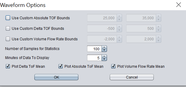
        In the below shared image , i have noticed the averaged mean volume flow rate also have some oscillation in whole number side. why i am raising this question because when i add one know flow gauge in serial its flow rate oscillation only in decimal places, but our ultrasonic design centre UI shows mean volume flow rate oscillation in both whole number and decimal places.

can you please clarify this occuacy level of ulrasonic design centre ?? or am i missing something ?
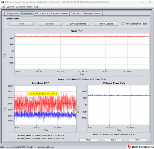
  • Hi,

    The volume flow rate are raw data. For a final product, it usually apply average function on the output of VFR. So, it looks more stable on a final product. You can also apply a filter on the output in software if necessary. 

    Best regards,

    Cash Hao

  • Hi Cash,
         Yes your correct, Volume flow rate is a raw data, and its have the some standard deviation as shows in ultrasonic design centre gui app. But that app also shows averaged data in the variable name of "Mean". Here my question is that mean value also have some oscillation in whole number.

    Already that Mean value take some time to get stable, i mean the response time was slow compare to our reference flow gauge. If i add some more filtering or postprocessing it will again increase the response time right ?? 

  • Hi,

    The mean value on the GUI takes 100 measurements and get the average results. You can change it in the GUI setting. 

    Best regards,

    Cash Hao

  • Hi cash, 

    Thanks for the respose. I have one more doubt about calculating the absolute time of flight. How the absolute time flight calculated ?? I have refered this below link
    https://e2e.ti.com/support/microcontrollers/msp-low-power-microcontrollers-group/msp430/f/msp-low-power-microcontroller-forum/1353789/msp430fr6043-meter-constant-doubt.

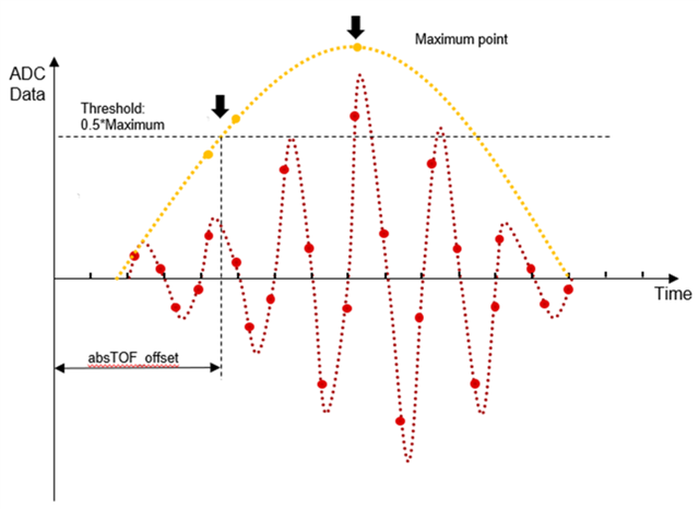
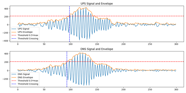
    In this link you have shared the detail about how the absolute time flight calculated. But i cant able to understand fully, by computing the envelope of the received signal through Hilbert transform. A maximum of the envelope for each capture is first computed. The envelope crossing as a given ratio of this maximum is then determined. From this point how to calculate the absolute time of flight ?

  • Hi,

    There is a figure in that post. 

    The absTOF result point is the intersection point of the threshold line and the yellow envelope line. We know the threshold value and the envelope data now. So, a simple interpolation can be used to calculate the absTOF result of this intersection point. 

    Best regards,

    Cash Hao

  • Hi Cash,
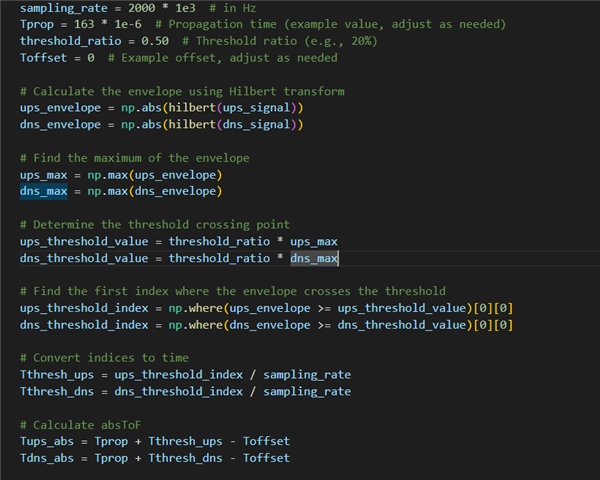
          For better understanding i try to compute the envelope as mentioned in user guide. 
                      

    Code Snippet,


    The above code snippet is my current implementation to calculate the absolute time of flight. Here, I am trying to find the max point of the envelop. from that max point we can get the 50% thershold point. To convert this index into time i try to divide the index by sampling rate the result will be a Tthresh_ups/Tthresh_dns. by adding the Tthresh_ups/Tthresh_dns value into Propagation time we can get the absolute time of flight right ?? or am i missing anything ?? because the calculated absolute time of flight looks not correct.

  • Hi,

    Your method look okay from my side. However, there are slight differences between your method and the one we used in USS library. The basic theory is similar though. 

    Best regards,

    Cash Hao

**Attention** This is a public forum