This thread has been locked.

If you have a related question, please click the "Ask a related question" button in the top right corner. The newly created question will be automatically linked to this question.

MSP430FR5987: MSP430FR5987 UART Configuration problem: Baud Rate 19200, Frequency 8MHz

Part Number: MSP430FR5987


Tool/software:

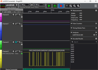
I'm snipping the data from the modbus system. I can see the value using logic analyser but it doesn't come up serial terminal. 

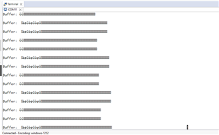
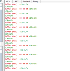
I tried to print normal string it's working but the data which in buffer never comes up to serial terminal?

Correct me if I'm wrong. The chip I'm using, MSP430FR5987, is inserted in a circuit that is for a specific project. Im using 19200 baud rate, is it the reason im not getting those buffer value in the serial terminal?

I've watched a video tutorial to mentioning that if i want to use baud rate higher than 9600, i have to use USB to UART converter (FT232RL). 

Looking for your valuable advise and suggestions.

Thanks

  • Some of the evaluation boards which have a "backside" serial channel over their USB connection do have limits on the bit rate. But it isn't clear if that applies here. You haven't really said how you are making that serial data connection.

  • I'm not sure; thats why posted here. I never worked on 19200 baud rate before but 4800 worked fine.

    #include <msp430.h>

    #define BUFFER_SIZE 256 // Size of buffer to hold captured Modbus frames
    #define TIMEOUT_THRESHOLD 14583 // 1.82 ms timeout at 8MHz clock for 19200

    volatile char bufferA[BUFFER_SIZE]; // Size of the buffer to hold captured Modbus frames
    volatile char bufferB[BUFFER_SIZE]; // Second buffer for Modbus data
    volatile char* activeBuffer = bufferA; // Active buffer pointer (initially bufferA)
    volatile char* sendBuffer = 0; // Buffer to send to host

    volatile unsigned int bufferIndex = 0; // Index to track buffer position in the active buffer
    volatile unsigned int modbusFrameComplete = 0; // Flag to indicate end of a frame
    volatile unsigned int bufferReadyToSend = 0; // Flag to indicate a buffer is ready to send

    // Function to configure UART for Modbus communication (19200 baud, 8N1)
    void configureClocks(void)
    {
    CSCTL0_H = CSKEY >> 8; // Unlock CS registers
    CSCTL1 = DCOFSEL_3 | DCORSEL; // Set DCO to 8MHz
    CSCTL2 = SELS__DCOCLK; // Set SMCLK = DCO
    CSCTL3 = DIVS__1; // Set SMCLK divider to 1
    CSCTL0_H = 0; // Lock CS registers
    }


    // UART function to transmit single byte

    void uartTransmitChar(char c){
    while(!(UCA1IFG & UCTXIFG)); // wait until the transmit buffer is empty
    UCA1TXBUF = c; // Send character
    }


    // UART function to transmit a string
    void uartTransmitString(const char * str){
    while(*str){ // Loop through the string until buffer is empty
    uartTransmitChar(*str); // Send each character
    str++; // Move to the next character
    }
    }

    // UART function to transmit the contents of a buffer
    void uartTransmitBuffer(const char* buffer, unsigned int length) {
    unsigned int i;
    uartTransmitString("\r\nBuffer: ");
    for (i = 0; i < length; i++) {
    uartTransmitChar(buffer[i]); // Send each byte in the buffer
    }
    uartTransmitString("\r\n"); // New line after buffer output
    }

    // UART function to transmit a single byte as a two-digit hex value
    void uartTransmitHexByte(unsigned char byte) {
    const char hexChars[] = "0123456789ABCDEF";
    uartTransmitChar(hexChars[(byte >> 4) & 0x0F]); // Send high nibble
    uartTransmitChar(hexChars[byte & 0x0F]); // Send low nibble
    }

    // UART function to transmit the contents of a buffer as hex
    void uartTransmitBufferHex(const char* buffer, unsigned int length) {
    unsigned int i;
    uartTransmitString("\r\nBuffer (Hex): ");
    for (i = 0; i < length; i++) {
    uartTransmitHexByte(buffer[i]); // Send each byte in hex
    uartTransmitChar(' '); // Add a space between bytes
    }
    uartTransmitString("\r\n"); // New line after buffer output
    }

    // Function to configure UART

    void configureUART()
    {
    // Set UART configuration: 19200 baud rate, 8 data bits, no parity, 1 stop bit
    UCA1CTL1 |= UCSWRST; // Put eUSCI in reset
    UCA1CTL1 |= UCSSEL_2; // SMCLK as clock source

    UCA1BRW = 26; // Baud rate 19200 for 8MHz clock

    UCA1MCTLW = (0x54 << 8) | (0x00 << 4) | UCOS16;; // Modulation UCBRSx=0xD6, UCBRFx=0, oversampling


    PM5CTL0 &= ~LOCKLPM5; // Turn on I/O
    UCA1CTL1 &= ~UCSWRST; // Initialize eUSCI
    UCA1IE |= UCRXIE; // Enable USCI_A1 RX interrupt
    UCA1IE |= UCTXIE;

    }


    void UARTRxTx(void){
    /*
    //P3.4(TXD) & P3.5(RXD)
    P3SEL0 |= BIT4 | BIT5; // Set P3.4 (TX) and P3.5 (RX) for UART mode (SEL0 = 1)
    P3SEL1 &= ~(BIT4 | BIT5); // Clear P3.3 and P3.4 in SEL1 (SEL1 = 0)
    */

    // Setup Ports
    P3SEL1 &= ~BIT4; // Clear P3SEL1 bit 4 (TXD)
    P3SEL0 |= BIT4; // Set P3SEL0 bit 4 (TXD)

    P3SEL1 &= ~BIT5; // Clear P3SEL1 bit 5 (RXD)
    P3SEL0 |= BIT5; // Set P3SEL0 bit 5 (RXD)

    }

    // Configure P3.0 as output to control LED
    void configureLED(void) {
    P3DIR |= BIT0; // Set P3.0 as output (LED)
    P3OUT &= ~BIT0; // Start with LED off
    }

    // Toggle the LED connected to P3.0
    void toggleLED(void) {
    P3OUT ^= BIT0; // Toggle P3.0 (LED)
    }

    // Example function to initialize RS485 transceiver in receive mode
    void configureRS485() {
    P3DIR |= BIT7; // Set RS485 DE (Driver Enable) pin as output
    P3OUT &= ~BIT7; // DE = 0 (receive mode)

    P3DIR |= BIT3; // Set RS485 RE (Receive Enable) pin as output
    P3OUT &= ~BIT3; // RE = 0 (receive mode)
    }

    void configureTimer(void){
    TA0CCTL0 = CCIE; // Enable interrupt for Timer_A capture/compare
    TA0CCR0 = TIMEOUT_THRESHOLD; // Set compare value for timeout (1.82 ms)
    TA0CTL =TASSEL_2 + MC_0; // Use SMCLK (8MHz), stop the timer initially
    }

    void startTimer(void){
    TA0R = 0; // Reset timer counter
    TA0CTL |= MC_1; // Start timer in up mode
    }

    void stopTimer(void){

    TA0CTL &= ~MC_1; // Stop the timer
    }

    // CRC16 calculation for Modbus (Polynomial: 0xA001)
    unsigned int calculateCRC16(const char* data, unsigned int length) {
    unsigned int crc = 0xFFFF; // Initialize CRC to 0xFFFF
    unsigned int i, j;

    for (i = 0; i < length; i++) {
    crc ^= data[i]; // XOR byte into the current CRC value
    for (j = 0; j < 8; j++) {
    if (crc & 0x0001) {
    crc >>= 1;
    crc ^= 0xA001; // Apply polynomial
    } else {
    crc >>= 1;
    }
    }
    }
    return crc;
    }

    // Example ISR for receiving Modbus data
    #pragma vector=USCI_A1_VECTOR
    __interrupt void USCI_A1_ISR(void) {
    if (UCA1IFG & UCRXIFG) { // Check if data has been received
    char receivedByte = UCA1RXBUF; // Read received data

    // Reset and start timer for timeout detection
    stopTimer();
    startTimer();


    //Store the received byte in buffer if there's space
    if(bufferIndex < BUFFER_SIZE){
    activeBuffer[bufferIndex++] = receivedByte;
    } else{
    // Reset buffer index to 1 (since byte is stored)
    }

    }
    }

    #pragma vector=TIMER_A0_VECTOR
    __interrupt void TIMER_A0_ISR(void){
    // Modbus frame timeout occurred (end of frame detected)
    stopTimer();

    //Signal that a Modbus frame has been captured and is ready for processing
    modbusFrameComplete = 1;

    //Swap buffers: make the current buffer ready to send and switch to the next buffer
    sendBuffer = activeBuffer; // Assign activeBuffer to sendBuffer
    bufferReadyToSend =1; //Flag to send buffer
    activeBuffer = (activeBuffer == bufferA)? bufferB:bufferA;
    bufferIndex = 0; // Reset the buffer index
    }

    void main(void) {
    WDTCTL = WDTPW | WDTHOLD; // Stop watchdog timer
    configureClocks();
    configureUART(); // Initialize UART
    UARTRxTx();
    configureRS485(); // Configure RS485 transceiver in receive mode
    configureTimer();


    __bis_SR_register(GIE); // Enable global interrupts
    while (1) {
    // Main loop: wait for modbus frame to be complete
    if(modbusFrameComplete){
    modbusFrameComplete= 0; //Reset frame complete flag
    //toggle LED
    toggleLED();

    uartTransmitBuffer(sendBuffer, bufferIndex); // // Send buffer content in hex
    bufferIndex = 0; // Reset buffer index for the next frame
    }
    }
    __bis_SR_register(LPM0_bits+GIE); // Enter low power mode, wait for interrupts
    }

  • UCA1IE |= UCTXIE;

    Remove this line. Your ISR doesn't use UCTXIFG, so the program will spend almost all of its time spinning through the ISR, and main won't make any progress.

  • removed but nothing coming though serial terminal I'm afraid. Can you suggest me in this case?

  • Your TIMER_A0_ISR sets modbusFrameComplete = 1 but also sets bufferIndex = 0 so by the time main sees it there is (appears to be) nothing to send.

    I suspect you want two different variables for these two uses.

  • I want to capture the data from modbus, even i can see the data in the logic analyser, im attaching it to you for your reference. 

  • CSCTL2 = SELS__DCOCLK; // Set SMCLK = DCO

    I'm pretty sure this sets MCLK=LFXTCLK (or maybe VLOCLK), which is quite(!) slow. This won't affect your UART, but it may perform poorly. Try instead:

    > CSCTL2 = SELS__DCOCLK|SELM__DCOCLK; // Set SMCLK = MCLK = DCO

    or maybe just don't set CSCTL2 at all. (Do set the dividers in CSCTL3 to /1, though.)

  • So you can see the data using the logic analyser but not on the serial terminal. Which means that you should be checking the connection to and configuration of the serial terminal.

    Although while serial terminals deal with printable ASCII characters pretty well, this non-printable stuff is a very different matter.

  • Why are you giving TransmitChar() a nibble? It works in characters/bytes.

    Also please post your code using code tags.

  • Each nybble converted to printable ASCII. This apparently being MODBUS rather than MODBUS RTU, which is binary. Although the logic analyzer data looks like binary.

  • #include <msp430.h>
    
    #define BUFFER_SIZE    256 // Size of buffer to hold captured Modbus frames
    #define TIMEOUT_THRESHOLD  14560  // 1.82 ms timeout at 8MHz clock for 19200
    
    volatile char bufferA[BUFFER_SIZE];  // Size of the buffer to hold captured Modbus frames
    volatile char bufferB[BUFFER_SIZE]; // Second buffer for Modbus data
    volatile char* activeBuffer = bufferA;  // Active buffer pointer (initially bufferA)
    volatile char* sendBuffer = 0;       // Buffer to send to host
    
    volatile unsigned int bufferIndex = 0;  // Index to track buffer position in the active buffer
    volatile unsigned int modbusFrameComplete = 0; // Flag to indicate end of a frame
    volatile unsigned int bufferReadyToSend = 0; // Flag to indicate a buffer is ready to send


    // Function to configure UART for Modbus communication (19200 baud, 8N1)
    void configureClocks(void)
    {
        CSCTL0_H = CSKEY >> 8;             // Unlock CS registers
        CSCTL1 = DCOFSEL_3 | DCORSEL;      // Set DCO to 8MHz
        CSCTL2 = SELS__DCOCLK;             // Set SMCLK = DCO
        CSCTL3 = DIVS__1;                  // Set SMCLK divider to 1
        CSCTL0_H = 0;                      // Lock CS registers
    }
    
    
    // UART function to transmit single byte
    
    void uartTransmitChar(char c){
        while(!(UCA1IFG & UCTXIFG)); // wait until the transmit buffer is empty
        UCA1TXBUF = c;          // Send character
    }
    
    
    // UART function to transmit a string
    void uartTransmitString(const char * str){
        while(*str){                // Loop through the string until buffer is empty
            uartTransmitChar(*str); // Send each character
            str++;          // Move to the next character
        }
    }
    
    // UART function to transmit the contents of a buffer
    void uartTransmitBuffer(const char* buffer, unsigned int length) {
        unsigned int i;
        uartTransmitString("\r\nBuffer: ");
        for (i = 0; i < length; i++) {
            uartTransmitChar(buffer[i]);  // Send each byte in the buffer
        }
        uartTransmitString("\r\n");       // New line after buffer output
    }
    
    // UART function to transmit a single byte as a two-digit hex value
    void uartTransmitHexByte(unsigned char byte) {
        const char hexChars[] = "0123456789ABCDEF";
        uartTransmitChar(hexChars[(byte >> 4) & 0x0F]);  // Send high nibble
        uartTransmitChar(hexChars[byte & 0x0F]);         // Send low nibble
    }
    
    // UART function to transmit the contents of a buffer as hex
    void uartTransmitBufferHex(const char* buffer, unsigned int length) {
        unsigned int i;
        uartTransmitString("\r\nBuffer (Hex): ");
        for (i = 0; i < length; i++) {
            uartTransmitHexByte(buffer[i]);  // Send each byte in hex
            uartTransmitChar(' ');           // Add a space between bytes
        }
        uartTransmitString("\r\n");          // New line after buffer output
    }


    // Function to configure UART
    
    void configureUART()
    {
        // Set UART configuration: 19200 baud rate, 8 data bits, no parity, 1 stop bit
        UCA1CTL1 |= UCSWRST;                    // Put eUSCI in reset
        UCA1CTL1 |= UCSSEL_2;                   // SMCLK as clock source
    
        UCA1BRW = 26;                          // Baud rate 19200 for 8MHz clock
    
        UCA1MCTLW = (0x54 << 8) | (0x00 << 4) | UCOS16;;                     // Modulation UCBRSx=0xD6, UCBRFx=0, oversampling
    
    
        PM5CTL0 &= ~LOCKLPM5;       // Turn on I/O
        UCA1CTL1 &= ~UCSWRST;                   // Initialize eUSCI
        UCA1IE |= UCRXIE;                       // Enable USCI_A1 RX interrupt
    
    }
    
    
    void UARTRxTx(void){
        /*
        //P3.4(TXD) & P3.5(RXD)
          P3SEL0 |= BIT4 | BIT5;     // Set P3.4 (TX) and P3.5 (RX) for UART mode (SEL0 = 1)
          P3SEL1 &= ~(BIT4 | BIT5);  // Clear P3.3 and P3.4 in SEL1 (SEL1 = 0)
          */
    
        // Setup Ports
        P3SEL1 &= ~BIT4;            // Clear P3SEL1 bit 4 (TXD)
        P3SEL0 |= BIT4;             // Set P3SEL0 bit 4 (TXD)
    
        P3SEL1 &= ~BIT5;            // Clear P3SEL1 bit 5 (RXD)
        P3SEL0 |= BIT5;             // Set P3SEL0 bit 5 (RXD)
    
    }
    
    // Configure P3.0 as output to control LED
    void configureLED(void) {
        P3DIR |= BIT0;    // Set P3.0 as output (LED)
        P3OUT &= ~BIT0;   // Start with LED off
    }
    
    // Toggle the LED connected to P3.0
    void toggleLED(void) {
        P3OUT ^= BIT0;    // Toggle P3.0 (LED)
    }
    
    // Example function to initialize RS485 transceiver in receive mode
    void configureRS485() {
        P3DIR |= BIT7;                          // Set RS485 DE (Driver Enable) pin as output
        P3OUT &= ~BIT7;                         // DE = 0 (receive mode)
    
        P3DIR |= BIT3;                          // Set RS485 RE (Receive Enable) pin as output
        P3OUT &= ~BIT3;                         // RE = 0 (receive mode)
    }
    
    void configureTimer(void){
        TA0CCTL0 = CCIE;                        // Enable interrupt for Timer_A capture/compare
        TA0CCR0 = TIMEOUT_THRESHOLD;            // Set compare value for timeout (1.82 ms)
        TA0CTL =TASSEL_2 + MC_0;                // Use SMCLK (8MHz), stop the timer initially
    }
    
    void startTimer(void){
        TA0R = 0;                               // Reset timer counter
        TA0CTL |= MC_1;                         // Start timer in up mode
    }
    
    void stopTimer(void){
    
        TA0CTL &= ~MC_1;                        // Stop the timer
    }
    
    // CRC16 calculation for Modbus (Polynomial: 0xA001)
    unsigned int calculateCRC16(const char* data, unsigned int length) {
        unsigned int crc = 0xFFFF;        // Initialize CRC to 0xFFFF
        unsigned int i, j;
    
        for (i = 0; i < length; i++) {
            crc ^= data[i];               // XOR byte into the current CRC value
            for (j = 0; j < 8; j++) {
                if (crc & 0x0001) {
                    crc >>= 1;
                    crc ^= 0xA001;        // Apply polynomial
                } else {
                    crc >>= 1;
                }
            }
        }
        return crc;
    }


    // Example ISR for receiving Modbus data
    #pragma vector=USCI_A1_VECTOR
    __interrupt void USCI_A1_ISR(void) {
        if (UCA1IFG & UCRXIFG) {                      // Check if data has been received
            char receivedByte = UCA1RXBUF;            // Read received data
    
            // Reset and start timer for timeout detection
            stopTimer();
            startTimer();
    
    
            //Store the received byte in buffer if there's space
            if(bufferIndex < BUFFER_SIZE){
                activeBuffer[bufferIndex++] = receivedByte;
    
            } else{
                           // Reset buffer index to 1 (since byte is stored)
            }
    
        }
    }
    
    #pragma vector=TIMER_A0_VECTOR
    __interrupt void TIMER_A0_ISR(void){
        // Modbus frame timeout occurred (end of frame detected)
        stopTimer();
    
        //Signal that a Modbus frame has been captured and is ready for processing
        //modbusFrameComplete = 1;
    
        //Swap buffers: make the current buffer ready to send and switch to the next buffer
        sendBuffer = activeBuffer;  // Assign activeBuffer to sendBuffer
        bufferReadyToSend =1;       //Flag to send buffer
        activeBuffer = (activeBuffer == bufferA)? bufferB:bufferA;
        //bufferIndex = 0;    // Reset the buffer index
    }
    
    void main(void) {
        WDTCTL = WDTPW | WDTHOLD;               // Stop watchdog timer
        configureClocks();
        configureUART();                        // Initialize UART
        UARTRxTx();
        configureRS485();                       // Configure RS485 transceiver in receive mode
        configureLED();
        configureTimer();
       // __bis_SR_register(GIE);                 // Enable global interrupts
        while (1) {
            // Main loop: wait for modbus frame to be complete
            if(modbusFrameComplete){
                modbusFrameComplete= 0;     //Reset frame complete flag
                //toggle LED
                toggleLED();
    
                uartTransmitBuffer(sendBuffer, bufferIndex); // // Send buffer content in hex
                bufferIndex = 0; // Reset buffer index for the next frame
                }
            }
            //__bis_SR_register(LPM0_bits+GIE);   // Enter low power mode, wait for interrupts
    }
    

  • No, in logic analyser its hexadecimal. and Im sure what im sending from pymodbus simulator, so what im sending im receiving same data. But it doesn't come up serial terminal. but i can see using logic analyser. Thats what my problem

  • Serial congifuration is okay, even i can print string using same configuration

  • > #pragma vector=TIMER_A0_VECTOR

    The compiler gave me a Warning on this line saying (effectively) that TIMER_A0_VECTOR isn't defined. Without an ISR, once the timeout expires, the program will go off to the "unknown IRQ" ISR and spin forever. Try instead:

    > #pragma vector=TIMER0_A0_VECTOR

  • used it #pragma vector = TIMER0_A0_VECTOR but no change

  • > // __bis_SR_register(GIE); // Enable global interrupts

    By removing this line, you prevent interrupts, so your UART (Rx) and timeout don't work. I recommend un-commenting this

    ----------------

    >  //modbusFrameComplete = 1;

    By removing this line, you prevent main from recognizing a completed frame.  I recommend un-commenting this.

    ------------------

    When I made these two fixes, it ran fine on my (FR6989) Launchpad. 

  • code is running, and i can see data using logic analyser but it doesn't come up to serial terminal

  • Did you put the logic analyzer on the serial output to make sure it is sending?

  • #include <msp430.h>
    
    #define BUFFER_SIZE    256 // Size of buffer to hold captured Modbus frames
    #define TIMEOUT_THRESHOLD  14560  // 1.82 ms timeout at 8MHz clock for 19200
    
    // Define state machine states
    typedef enum {
        STATE_IDLE,
        STATE_RECEIVE_FRAME,
        STATE_PROCESS_FRAME,
        STATE_TRANSMIT_BUFFER
    } SystemState;
    
    volatile char bufferA[BUFFER_SIZE];  // Size of the buffer to hold captured Modbus frames
    volatile char bufferB[BUFFER_SIZE];  // Second buffer for Modbus data
    volatile char* activeBuffer = bufferA;  // Active buffer pointer (initially bufferA)
    volatile char* sendBuffer = 0;       // Buffer to send to host
    
    volatile unsigned int bufferIndex = 0;  // Index to track buffer position in the active buffer
    volatile unsigned int bufferReadyToSend = 0; // Flag to indicate a buffer is ready to send
    SystemState currentState = STATE_IDLE;  // Initialize state to IDLE
    
    // Function to configure UART for Modbus communication (19200 baud, 8N1)
    void configureClocks(void) {
        CSCTL0_H = CSKEY >> 8;             // Unlock CS registers
        CSCTL1 = DCOFSEL_3 | DCORSEL;      // Set DCO to 8MHz
        CSCTL2 = SELS__DCOCLK;             // Set SMCLK = DCO
        CSCTL3 = DIVS__1;                  // Set SMCLK divider to 1
        CSCTL0_H = 0;                      // Lock CS registers
    }
    
    // UART function to transmit single byte
    void uartTransmitChar(char c) {
        while (!(UCA1IFG & UCTXIFG)); // Wait until the transmit buffer is empty
        UCA1TXBUF = c;                // Send character
    }
    
    // UART function to transmit a string
    void uartTransmitString(const char* str) {
        while (*str) {                // Loop through the string until buffer is empty
            uartTransmitChar(*str);   // Send each character
            str++;                    // Move to the next character
        }
    }
    
    // UART function to transmit the contents of a buffer
    void uartTransmitBuffer(const char* buffer, unsigned int length) {
        unsigned int i;
        uartTransmitString("\r\nBuffer: ");
        for (i = 0; i < length; i++) {
            uartTransmitChar(buffer[i]);  // Send each byte in the buffer
        }
        uartTransmitString("\r\n");       // New line after buffer output
    }
    
    // UART function to transmit a single byte as a two-digit hex value
    void uartTransmitHexByte(unsigned char byte) {
        const char hexChars[] = "0123456789ABCDEF";
        uartTransmitChar(hexChars[(byte >> 4) & 0x0F]);  // Send high nibble
        uartTransmitChar(hexChars[byte & 0x0F]);         // Send low nibble
    }
    
    // UART function to transmit the contents of a buffer as hex
    void uartTransmitBufferHex(const char* buffer, unsigned int length) {
        unsigned int i;
        uartTransmitString("\r\nBuffer (Hex): ");
        for (i = 0; i < length; i++) {
            uartTransmitHexByte(buffer[i]);  // Send each byte in hex
            uartTransmitChar(' ');           // Add a space between bytes
        }
        uartTransmitString("\r\n");          // New line after buffer output
    }
    
    // Function to configure UART
    void configureUART() {
        // Set UART configuration: 19200 baud rate, 8 data bits, no parity, 1 stop bit
        UCA1CTL1 |= UCSWRST;                    // Put eUSCI in reset
        UCA1CTL1 |= UCSSEL_2;                   // SMCLK as clock source
    
        UCA1BRW = 26;                           // Baud rate 19200 for 8MHz clock
        UCA1MCTLW = (0x54 << 8) | (0x00 << 4) | UCOS16; // Modulation oversampling
    
        PM5CTL0 &= ~LOCKLPM5;       // Turn on I/O
        UCA1CTL1 &= ~UCSWRST;                   // Initialize eUSCI
        UCA1IE |= UCRXIE;                       // Enable USCI_A1 RX interrupt
    }
    
    void UARTRxTx(void) {
        // Setup Ports
        P3SEL1 &= ~BIT4;            // Clear P3SEL1 bit 4 (TXD)
        P3SEL0 |= BIT4;             // Set P3SEL0 bit 4 (TXD)
    
        P3SEL1 &= ~BIT5;            // Clear P3SEL1 bit 5 (RXD)
        P3SEL0 |= BIT5;             // Set P3SEL0 bit 5 (RXD)
    }
    
    // Configure P3.0 as output to control LED
    void configureLED(void) {
        P3DIR |= BIT0;    // Set P3.0 as output (LED)
        P3OUT &= ~BIT0;   // Start with LED off
    }
    
    // Toggle the LED connected to P3.0
    void toggleLED(void) {
        P3OUT ^= BIT0;    // Toggle P3.0 (LED)
    }
    
    // Example function to initialize RS485 transceiver in receive mode
    void configureRS485() {
        P3DIR |= BIT7;                          // Set RS485 DE (Driver Enable) pin as output
        P3OUT &= ~BIT7;                         // DE = 0 (receive mode)
    
        P3DIR |= BIT3;                          // Set RS485 RE (Receive Enable) pin as output
        P3OUT &= ~BIT3;                         // RE = 0 (receive mode)
    }
    
    void configureTimer(void) {
        TA0CCTL0 = CCIE;                        // Enable interrupt for Timer_A capture/compare
        TA0CCR0 = TIMEOUT_THRESHOLD;            // Set compare value for timeout (1.82 ms)
        TA0CTL = TASSEL_2 + MC_0;               // Use SMCLK (8MHz), stop the timer initially
    }
    
    void startTimer(void) {
        TA0R = 0;                               // Reset timer counter
        TA0CTL |= MC_1;                         // Start timer in up mode
    }
    
    void stopTimer(void) {
        TA0CTL &= ~MC_1;                        // Stop the timer
    }
    
    // CRC16 calculation for Modbus (Polynomial: 0xA001)
    unsigned int calculateCRC16(const char* data, unsigned int length) {
        unsigned int crc = 0xFFFF;        // Initialize CRC to 0xFFFF
        unsigned int i, j;
    
        for (i = 0; i < length; i++) {
            crc ^= data[i];               // XOR byte into the current CRC value
            for (j = 0; j < 8; j++) {
                if (crc & 0x0001) {
                    crc >>= 1;
                    crc ^= 0xA001;        // Apply polynomial
                } else {
                    crc >>= 1;
                }
            }
        }
        return crc;
    }
    
    // Example ISR for receiving Modbus data
    #pragma vector=USCI_A1_VECTOR
    __interrupt void USCI_A1_ISR(void) {
        if (UCA1IFG & UCRXIFG) {                      // Check if data has been received
            char receivedByte = UCA1RXBUF;            // Read received data
    
            // Reset and start timer for timeout detection
            stopTimer();
            startTimer();
    
            // Store the received byte in buffer if there's space
            if (bufferIndex < BUFFER_SIZE) {
                activeBuffer[bufferIndex++] = receivedByte;
            }
        }
    }
    
    #pragma vector=TIMER0_A0_VECTOR
    __interrupt void TIMER_A0_ISR(void) {
        // Modbus frame timeout occurred (end of frame detected)
        stopTimer();
        //modbusFrameComplete = 1;
        // Indicate the buffer is ready to send, and set the current buffer as the send buffer
        bufferReadyToSend = 1; // Set the flag to signal the main loop
    
        // Swap buffers: make the current buffer ready to send and switch to the next buffer
        sendBuffer = activeBuffer;          // Assign activeBuffer to sendBuffer
        activeBuffer = (activeBuffer == bufferA) ? bufferB : bufferA;  // Switch to the other buffer
        //bufferIndex = 0;                    // Reset the buffer index
    }
    
    void main(void) {
        WDTCTL = WDTPW | WDTHOLD;           // Stop watchdog timer
        configureClocks();
        configureUART();                    // Initialize UART
        UARTRxTx();
        configureRS485();                   // Configure RS485 transceiver in receive mode
        configureLED();
        configureTimer();
        __bis_SR_register(GIE);             // Enable global interrupts
    
        while (1) {
            switch (currentState) {
                case STATE_IDLE:
                    // Waiting for buffer to be ready
                    if (bufferReadyToSend) {
                        bufferReadyToSend = 0;
                        currentState = STATE_PROCESS_FRAME;  // Move to processing state
                    }
                    break;
    
                case STATE_PROCESS_FRAME:
    
                    currentState = STATE_TRANSMIT_BUFFER;  // Move to transmit state
                    break;
    
                case STATE_TRANSMIT_BUFFER:
                    uartTransmitBuffer(sendBuffer, bufferIndex);  // Transmit buffer contents
                    toggleLED();                           // Indicate frame processing
                    currentState = STATE_IDLE;            // Return to idle state
                    break;
    
                default:
                    currentState = STATE_IDLE;            // Fallback to idle in case of unexpected state
                    break;
            }
        }
    }
    

    Right now problem is. and if i show you the logic analyser

  • I'm not sure what you're concerned about. What were you expecting to see?

  • Can you see the update in console?
    I want full frame

  • OK, I don't see this output with the code you posted. It looks as though you're only getting fragments (last 3 maybe?) of each packet.

    As I mentioned before, your CPU is running very slowly -- on my Launchpad I measure MCLK=37kHz, which only gives you about 18 CPU clocks (maybe 3 instructions) per byte and in this test case they arrive back-to-back. Are you seeing Overruns (UCOE)?

  • Im running 8MHz and 19200 baud rate. I don't understand about clock speed, im totally new to msp430. 
    However, I figured out to this journey till now but i need to get full frame.
    full frame is 0x01 0x03 0x0E 0x00 0x11 0x00 0x00 0x00 0x00 0x00 0x00 0x00 0x00 0x00 0x00 0x00 0x00 0xD3 0X04

  • Try removing this line:

    >  CSCTL2 = SELS__DCOCLK; // Set SMCLK = DCO

    and see if you get different results.

  • You're absolutely right. Now I'm receiving full frame. 
    Thanks a lot. Can I  have your email id?

  • I'm glad you got it working.

    I think it's best to keep these discussions in the Forum. That way many people can contribute.

**Attention** This is a public forum