This thread has been locked.

If you have a related question, please click the "Ask a related question" button in the top right corner. The newly created question will be automatically linked to this question.

MSP430F6779A: Why is the leakage current of I/O so high (floating input)?

Part Number: MSP430F6779A


Tool/software:


I tested the current consumption when setting the MCU in LPM3 mode.

Configuration #1: unused pins to inputs and disable internal pull-up resistors (P4.1 to P4.6)
result: current consumption is 8 uA

Configuration #2: Set unused pins to low outputs (P4.1 to P4.6)
result: current consumption is 200 uA

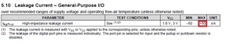
Why is the leakage current I/O so high (expected 0.3 uA)?

  • corrected

    Configuration #1: unused pins to inputs and disable internal pull-up resistors (P4.1 to P4.6)
    result: current consumption is 200 uA

    Configuration #2: Set unused pins to low outputs (P4.1 to P4.6)
    result: current consumption is 8 uA

  • Did you connect those input pins to Vss or Vcc? (see note)

    You never want to leave CMOS inputs floating which is why the recommendation in the principles of low power operation section is to set unused pins to outputs.

  • No, I just measured the current of the Vcc pin.

    I would like to know why the current is so high when the I/O is configured as a floating input (i.e. noise or something).

    Is it possible to estimate this current (in case there is a floating input in the system)?

  • The current is high because the floating gates collect charge and can end up at a voltage where both the N and P channel FETs aren't completely off. Connecting Vcc to Vss.

    This is a well known characteristic of CMOS.

**Attention** This is a public forum