This thread has been locked.

If you have a related question, please click the "Ask a related question" button in the top right corner. The newly created question will be automatically linked to this question.

MSP430FR2676: lighting up neopixel leds using MSP430FR2676

Part Number: MSP430FR2676

Tool/software:

Hi Team,

I am trying to replicate the functioning of adafruit neopixel leds using MSP430FR2676. I found a library online (MSP430-NeoPixel-WS2812-Library/README.md at master · mjmeli/MSP430-NeoPixel-WS2812-Library · GitHub) which had been already discussed in this forum and tried to edit it according to the datasheet of MSP430FR2676. However I wasnt able to turn on the leds. Could you please help on this I have attached the code below. 

Many thanks,
Criton

#include <msp430.h>

#define OUTPUT_PIN	(0x04)  //px.2 on msp430fr2676
#define NUM_LEDS    (12)    // NUMBER OF LEDS IN YOUR STRIP

// Useful typedefs
typedef unsigned char u_char;	// 8 bit
typedef unsigned int u_int;     // 16 bit
// Transmit codes
#define HIGH_CODE	(0xF0)      // b11110000 
#define LOW_CODE    (0xC0)      // b11000000
// Configure processor to output to data strip
void initStrip(void);
// Send colors to the strip and show them. Disables interrupts while processing.
void showStrip(void);
// Set the color of a certain LED
void setLEDColor(u_int p, u_char r, u_char g, u_char b);
// Clear the color of all LEDs (make them black/off)
void clearStrip(void);
// Fill the strip with a solid color. This will update the strip.
void fillStrip(u_char r, u_char g, u_char b);

#include <msp430.h>
#include "msp430fr2676.h"
#include "rgb.h"

typedef struct {
    u_char red;
    u_char green;
    u_char blue;
} LED;

LED leds[NUM_LEDS] = { { 0, 0, 0 } };

// Initializes everything needed to use this library. This clears the strip.
void initStrip()
{
    P1SEL0 |= BIT4 | BIT5 | BIT6;

    FRCTL0 = FRCTLPW | NWAITS_1;

    __bis_SR_register(SCG0);    // disable FLL
    CSCTL3 |= SELREF__REFOCLK;  // Set REFO as FLL reference source
    CSCTL0 = 0;                 // clear DCO and MOD registers
    CSCTL1 &= ~(DCORSEL_7);     // Clear DCO frequency select bits first
    CSCTL1 |= DCORSEL_5;        // Set DCO = 16MHz
    CSCTL2 = FLLD_0 + 487;      // set to fDCOCLKDIV = (FLLN + 1)*(fFLLREFCLK/n)
                                //                   = (487 + 1)*(32.768 kHz/1)
                                //                   = 16 MHz

    __delay_cycles(3);
    __bic_SR_register(SCG0);                        // enable FLL
    while(CSCTL7 & (FLLUNLOCK0 | FLLUNLOCK1));      // FLL locked
    clearStrip();   
}

// Sets the color of a certain LED (0 indexed)
void setLEDColor(u_int p, u_char r, u_char g, u_char b) {
    leds[p].red = r;
    leds[p].green = g;
    leds[p].blue = b;
}

// Send colors to the strip and show them. Disables interrupts while processing.
void showStrip() {
    __bic_SR_register(GIE);           // disable interrupts
    // send RGB color for every LED
    int i, j;
    for (i = 0; i < NUM_LEDS; i++) {

        u_char rgb[3] = { leds[i].green, leds[i].red, leds[i].blue }; // get RGB color for this LED
        // send green, then red, then blue
        for (j = 0; j < 3; j++) {
        u_char mask = 0x04;    // b0000100

            while (mask != 0) { 
                 while (! UCB0IFG)
                 ;
                 if (rgb[j] & mask) {        // most significant bit first
                    UCB0TXBUF = HIGH_CODE;  // send 1
                } else {
                    UCB0TXBUF = LOW_CODE;   // send 0
                }
                 mask >>= 1;  // check next bit
            }
        }
    }
    // send RES code for at least 50 us (800 cycles at 16 MHz)
    __delay_cycles(800);
    __bis_SR_register(GIE);    // enable interrupts
}

// Clear the color of all LEDs (make them black/off)
void clearStrip() {
    fillStrip(0x00, 0x00, 0x00);  // black
}

// Fill the strip with a solid color. This will update the strip.
void fillStrip(u_char r, u_char g, u_char b) {
    int i;
    for (i = 0; i < NUM_LEDS; i++) {
        setLEDColor(i, r, g, b);  // set all LEDs to specified color
    }
    showStrip();  // refresh strip
}

void gradualFill(u_int n, u_char r, u_char g, u_char b);

int main(void) {

      WDTCTL = WDTPW | WDTHOLD; 

      initStrip();
      fillStrip(0xFF, 0x00, 0x00);
      showStrip();
     
     while (1) {
        gradualFill(NUM_LEDS, 0x00, 0xFF, 0x00);  // green
        gradualFill(NUM_LEDS, 0x00, 0x00, 0xFF);  // blue
        gradualFill(NUM_LEDS, 0xFF, 0x00, 0xFF);  // magenta
        gradualFill(NUM_LEDS, 0xFF, 0xFF, 0x00);  // yellow
        gradualFill(NUM_LEDS, 0x00, 0xFF, 0xFF);  // cyan
        gradualFill(NUM_LEDS, 0xFF, 0x00, 0x00);  // red
    }
}
void gradualFill(u_int n, u_char r, u_char g, u_char b){
    int i;
    for (i = 0; i < n; i++){        // n is number of LEDs
        setLEDColor(i, r, g, b);
        showStrip();
                _delay_cycles(1000000);       // lazy delay
    }
}

  • Just by inspection, I see a couple of pieces missing:

    1) There's nothing to configure UCB0. Translating from the original, this might look something like:

        P1SEL0 |= OUTPUT_PIN;    // configure output pin as SPI output
        P1SEL1 &= ~OUTPUT_PIN;   // P1.2 as UCB0SIMO per SLASEO5D Table 9-23
        UCB0CTLW0 |= UCCKPH + UCMSB + UCMST + UCSYNC + UCSSEL_2; // 3-pin, MSB, 8-bit SPI master
        UCB0BR0 = 3;            // 16 MHz / 3 = .1875 us per bit
        UCB0BR1 = 0;
        UCB0CTLW0 &= ~UCSWRST;   // Initialize USCI state machine
    

    I've chosen P1.2 for you. UCB0SIMO is also available on P4.6

    2) In the line

    >  while (! UCB0IFG)

    The IFG register may have other bits set. Try instead:

                    while (!(UCB0IFG & UCTXIFG))
    

    I haven't tried this (I don't have one of those devices) but I think it's about right.

  • Hi Bruce,

    Many thanks for getting in touch. I made these changes still does light up. I have tried connecting the signal pin to p1.2 and p4.6. I have attached the code for your reference.

    Many thanks and Kind regards,
    Criton


    #include <msp430.h>
    #include "msp430fr2676.h"
    #include "rgb.h"
    
    typedef struct {
        u_char red;
        u_char green;
        u_char blue;
    } LED;
    
    LED leds[NUM_LEDS] = { { 0, 0, 0 } };
    
    // Initializes everything needed to use this library. This clears the strip.
    void initStrip()
    {
        P1SEL0 |= OUTPUT_PIN;    // configure output pin as SPI output
        P1SEL1 &= ~OUTPUT_PIN;   // P1.2 as UCB0SIMO per SLASEO5D Table 9-23
        UCB0CTLW0 |= UCCKPH + UCMSB + UCMST + UCSYNC + UCSSEL_2; // 3-pin, MSB, 8-bit SPI master
        UCB0BR0 = 3;            // 16 MHz / 3 = .1875 us per bit
        UCB0BR1 = 0;
        UCB0CTLW0 &= ~UCSWRST;   // Initialize USCI state machine
        clearStrip();   
    }
    
    // Sets the color of a certain LED (0 indexed)
    void setLEDColor(u_int p, u_char r, u_char g, u_char b) {
        leds[p].red = r;
        leds[p].green = g;
        leds[p].blue = b;
    }
    
    // Send colors to the strip and show them. Disables interrupts while processing.
    void showStrip() {
        __bic_SR_register(GIE);           // disable interrupts
        // send RGB color for every LED
        int i, j;
        for (i = 0; i < NUM_LEDS; i++) {
    
            u_char rgb[3] = { leds[i].green, leds[i].red, leds[i].blue }; // get RGB color for this LED
            // send green, then red, then blue
            for (j = 0; j < 3; j++) {
            u_char mask = 0x04;    // b0000100
    
                while (mask != 0) { 
                     while (!(UCB0IFG & UCTXIFG))
                     ;
                     if (rgb[j] & mask) {        // most significant bit first
                        UCB0TXBUF = HIGH_CODE;  // send 1
                    } else {
                        UCB0TXBUF = LOW_CODE;   // send 0
                    }
                     mask >>= 1;  // check next bit
                }
            }
        }
        // send RES code for at least 50 us (800 cycles at 16 MHz)
        __delay_cycles(800);
        __bis_SR_register(GIE);    // enable interrupts
    }
    
    // Clear the color of all LEDs (make them black/off)
    void clearStrip() {
        fillStrip(0x00, 0x00, 0x00);  // black
    }
    
    // Fill the strip with a solid color. This will update the strip.
    void fillStrip(u_char r, u_char g, u_char b) {
        int i;
        for (i = 0; i < NUM_LEDS; i++) {
            setLEDColor(i, r, g, b);  // set all LEDs to specified color
        }
        showStrip();  // refresh strip
    }
    
    void gradualFill(u_int n, u_char r, u_char g, u_char b);
    
    int main(void) {
    
          WDTCTL = WDTPW | WDTHOLD; 
    
          initStrip();
          fillStrip(0xFF, 0xFF, 0xFF);
          showStrip();
        
         while (1) {
            gradualFill(NUM_LEDS, 0x00, 0xFF, 0x00);  // green
            gradualFill(NUM_LEDS, 0x00, 0x00, 0xFF);  // blue
            gradualFill(NUM_LEDS, 0xFF, 0x00, 0xFF);  // magenta
            gradualFill(NUM_LEDS, 0xFF, 0xFF, 0x00);  // yellow
            gradualFill(NUM_LEDS, 0x00, 0xFF, 0xFF);  // cyan
            gradualFill(NUM_LEDS, 0xFF, 0x00, 0x00);  // red
        }
    }
    void gradualFill(u_int n, u_char r, u_char g, u_char b){
        int i;
        for (i = 0; i < n; i++){        // n is number of LEDs
            setLEDColor(i, r, g, b);
            showStrip();
                    _delay_cycles(1000000);       // lazy delay
        }
    }

  • It looks as though you lost the code that sets the CPU clock (really SMCLK) to 16MHz. ("FRCTL=" down through "while (CSCTL7".)

    That code probably belongs in main() anyway.

  • HI :),

    I didnt understand what you just explained. are you talking about the piece of code removed from the initial one which I sent that sets the clock for 16MHz? Should I keep it and try?. 

  • Yes, you should put that sequence back, though probably in main() rather than in initStrip().

    Out of reset, the MCU clock (MCLK/SMCLK) runs at 1MHz, which as the author points out is too slow to get the correct bit timings. I imagine that at the lower speed everything looks like a RES pulse.

  • Thank you for getting back to me promptly. but it will have the same effect if I do it in a function as it is passed in main right? I have called it in main however still the same thing it does not light up.

    I have attached the code for your reference.

    Kind regardds,
    Criton

    #include <msp430.h>
    #include "msp430fr2676.h"
    #include "rgb.h"
    
    typedef struct {
        u_char red;
        u_char green;
        u_char blue;
    } LED;
    
    LED leds[NUM_LEDS] = { { 0, 0, 0 } };
    
    // Initializes everything needed to use this library. This clears the strip.
    void initStrip()
    {
        P1SEL0 |= OUTPUT_PIN;    // configure output pin as SPI output
        P1SEL1 &= ~OUTPUT_PIN;   // P1.2 as UCB0SIMO per SLASEO5D Table 9-23
        UCB0CTLW0 |= UCCKPH + UCMSB + UCMST + UCSYNC + UCSSEL_2; // 3-pin, MSB, 8-bit SPI master
        UCB0BR0 = 3;            // 16 MHz / 3 = .1875 us per bit
        UCB0BR1 = 0;
        UCB0CTLW0 &= ~UCSWRST;   // Initialize USCI state machine
        clearStrip();   
    }
    
    // Sets the color of a certain LED (0 indexed)
    void setLEDColor(u_int p, u_char r, u_char g, u_char b) {
        leds[p].red = r;
        leds[p].green = g;
        leds[p].blue = b;
    }
    
    // Send colors to the strip and show them. Disables interrupts while processing.
    void showStrip() {
        __bic_SR_register(GIE);           // disable interrupts
        // send RGB color for every LED
        int i, j;
        for (i = 0; i < NUM_LEDS; i++) {
    
            u_char rgb[3] = { leds[i].green, leds[i].red, leds[i].blue }; // get RGB color for this LED
            // send green, then red, then blue
            for (j = 0; j < 3; j++) {
            u_char mask = 0x04;    // b0000100
    
                while (mask != 0) { 
                     while (!(UCB0IFG & UCTXIFG))
                     ;
                     if (rgb[j] & mask) {        // most significant bit first
                        UCB0TXBUF = HIGH_CODE;  // send 1
                    } else {
                        UCB0TXBUF = LOW_CODE;   // send 0
                    }
                     mask >>= 1;  // check next bit
                }
            }
        }
        // send RES code for at least 50 us (800 cycles at 16 MHz)
        __delay_cycles(800);
        __bis_SR_register(GIE);    // enable interrupts
    }
    
    // Clear the color of all LEDs (make them black/off)
    void clearStrip() {
        fillStrip(0x00, 0x00, 0x00);  // black
    }
    
    // Fill the strip with a solid color. This will update the strip.
    void fillStrip(u_char r, u_char g, u_char b) {
        int i;
        for (i = 0; i < NUM_LEDS; i++) {
            setLEDColor(i, r, g, b);  // set all LEDs to specified color
        }
        showStrip();  // refresh strip
    }
    
    void gradualFill(u_int n, u_char r, u_char g, u_char b);
    
    int main(void) {
    
          WDTCTL = WDTPW | WDTHOLD; 
    
            initStrip();
            __bis_SR_register(SCG0);    // disable FLL
            CSCTL3 |= SELREF__REFOCLK;  // Set REFO as FLL reference source
            CSCTL0 = 0;                 // clear DCO and MOD registers
            CSCTL1 &= ~(DCORSEL_7);     // Clear DCO frequency select bits first
            CSCTL1 |= DCORSEL_5;        // Set DCO = 16MHz
            CSCTL2 = FLLD_0 + 487;      // set to fDCOCLKDIV = (FLLN + 1)*(fFLLREFCLK/n)
                                    //                   = (487 + 1)*(32.768 kHz/1)
                                    //                   = 16 MHz
    
            __delay_cycles(3);
            __bic_SR_register(SCG0);                        // enable FLL
            while(CSCTL7 & (FLLUNLOCK0 | FLLUNLOCK1));      // FLL locked
            fillStrip(0xFF, 0xFF, 0xFF);
            showStrip();
        
         while (1) {
            gradualFill(NUM_LEDS, 0x00, 0xFF, 0x00);  // green
            gradualFill(NUM_LEDS, 0x00, 0x00, 0xFF);  // blue
            gradualFill(NUM_LEDS, 0xFF, 0x00, 0xFF);  // magenta
            gradualFill(NUM_LEDS, 0xFF, 0xFF, 0x00);  // yellow
            gradualFill(NUM_LEDS, 0x00, 0xFF, 0xFF);  // cyan
            gradualFill(NUM_LEDS, 0xFF, 0x00, 0x00);  // red
        }
    }
    void gradualFill(u_int n, u_char r, u_char g, u_char b){
        int i;
        for (i = 0; i < n; i++){        // n is number of LEDs
            setLEDColor(i, r, g, b);
            showStrip();
                    _delay_cycles(1000000);       // lazy delay
        }
    }

  • You should probably set up the clock before calling initStrip rather than after. This would only affect the initial clearStrip call, though.

    Something else I noticed is missing (the author wouldn't have had to do this on a F2/G2 device, but it's needed for FRx devices):

    > PM5CTL0 &= ~LOCKLPM5;   // Engage GPIOs

    You can do this any time before the initStrip call.

    Are you fairly certain your strip is powered properly? I (vaguely) recall that a strip of 12x draws a fair amount of power.

  • Hi bruce,

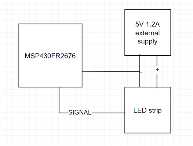
    Many thanks for your response I have attached my code and circuit connections for your reference. Indeed i am using an external power supply to power the LEDS. however even after modifying the code the leds dont light the way they should. I also tried changing the number of LEDs used in the header to a few numbers.

    Kind regards,
    Criton

    #include <msp430.h>
    #include "msp430fr2676.h"
    #include "rgb.h"
    
    typedef struct {
        u_char red;
        u_char green;
        u_char blue;
    } LED;
    
    LED leds[NUM_LEDS] = { { 0, 0, 0 } };
    
    // Initializes everything needed to use this library. This clears the strip.
    void initStrip()
    {
        P1SEL0 |= OUTPUT_PIN;    // configure output pin as SPI output
        P1SEL1 &= ~OUTPUT_PIN;   // P1.2 as UCB0SIMO per SLASEO5D Table 9-23
        UCB0CTLW0 |= UCCKPH + UCMSB + UCMST + UCSYNC + UCSSEL_2; // 3-pin, MSB, 8-bit SPI master
        UCB0BR0 = 3;            // 16 MHz / 3 = .1875 us per bit
        UCB0BR1 = 0;
        UCB0CTLW0 &= ~UCSWRST;   // Initialize USCI state machine
        clearStrip();   
    }
    
    // Sets the color of a certain LED (0 indexed)
    void setLEDColor(u_int p, u_char r, u_char g, u_char b) {
        leds[p].red = r;
        leds[p].green = g;
        leds[p].blue = b;
    }
    
    // Send colors to the strip and show them. Disables interrupts while processing.
    void showStrip() {
        __bic_SR_register(GIE);           // disable interrupts
        // send RGB color for every LED
        int i, j;
        for (i = 0; i < NUM_LEDS; i++) {
    
            u_char rgb[3] = { leds[i].green, leds[i].red, leds[i].blue }; // get RGB color for this LED
            // send green, then red, then blue
            for (j = 0; j < 3; j++) {
            u_char mask = 0x04;    // b0000100
    
                while (mask != 0) { 
                     while (!(UCB0IFG & UCTXIFG))
                     ;
                     if (rgb[j] & mask) {        // most significant bit first
                        UCB0TXBUF = HIGH_CODE;  // send 1
                    } else {
                        UCB0TXBUF = LOW_CODE;   // send 0
                    }
                     mask >>= 1;  // check next bit
                }
            }
        }
        // send RES code for at least 50 us (800 cycles at 16 MHz)
        __delay_cycles(800);
        __bis_SR_register(GIE);    // enable interrupts
    }
    
    // Clear the color of all LEDs (make them black/off)
    void clearStrip() {
        fillStrip(0x00, 0x00, 0x00);  // black
    }
    
    // Fill the strip with a solid color. This will update the strip.
    void fillStrip(u_char r, u_char g, u_char b) {
        int i;
        for (i = 0; i < NUM_LEDS; i++) {
            setLEDColor(i, r, g, b);  // set all LEDs to specified color
        }
        showStrip();  // refresh strip
    }
    
    void gradualFill(u_int n, u_char r, u_char g, u_char b);
    
    int main(void) {
    
          WDTCTL = WDTPW | WDTHOLD;  
    
            CSCTL3 |= SELREF__REFOCLK;  // Set REFO as FLL reference source
            CSCTL0 = 0;                 // clear DCO and MOD registers
            CSCTL1 &= ~(DCORSEL_7);     // Clear DCO frequency select bits first
            CSCTL1 |= DCORSEL_5;        // Set DCO = 16MHz
            CSCTL2 = FLLD_0 + 487;      // set to fDCOCLKDIV = (FLLN + 1)*(fFLLREFCLK/n)
                                    //                   = (487 + 1)*(32.768 kHz/1)
                                    //                   = 16 MHz
    
            __delay_cycles(3);
            __bic_SR_register(SCG0);                        // enable FLL  
            PM5CTL0 &= ~LOCKLPM5; 
            initStrip();
            fillStrip(0xFF, 0xFF, 0xFF);
            showStrip();
            clearStrip();
        
         while (1) {
            gradualFill(NUM_LEDS, 0x00, 0xFF, 0x00);  // green
            gradualFill(NUM_LEDS, 0x00, 0x00, 0xFF);  // blue
            gradualFill(NUM_LEDS, 0xFF, 0x00, 0xFF);  // magenta
            gradualFill(NUM_LEDS, 0xFF, 0xFF, 0x00);  // yellow
            gradualFill(NUM_LEDS, 0x00, 0xFF, 0xFF);  // cyan
            gradualFill(NUM_LEDS, 0xFF, 0x00, 0x00);  // red
        }
    }
    void gradualFill(u_int n, u_char r, u_char g, u_char b){
        int i;
        for (i = 0; i < n; i++){        // n is number of LEDs
            setLEDColor(i, r, g, b);
            showStrip();
                    _delay_cycles(1000000);       // lazy delay
        }
    }


  • I also forgot to mention the leds dont change colour they just stay lit white. when I give number of leds=50 15 leds light up white and stay as it is they do change the colour as defined in the while(1) loop.

  • >  u_char mask = 0x04; // b0000100

    This only sends 3 bits/color, but the original code starts with a mask of 0x80, so it sends 8 bits/color. (The number 8 also matches with my copy of the WS2812B data sheet.)

    Is there a reason you changed this?

  • OOps that was a typo.

    But that does not resolve the problem.

  • it more of like the leds turn on and stay there even if I press reset on the msp. more of like if I keep number of led =10, 9 glows up out of which 8 is white and the 9th one is sort of green. when I make it to 20, 16 leds goes white and 4 stays off.

    Many thanks 

  • I'm looking at that core loop (that writes the SPI) and really wondering if it is able to keep up the pace. Each cycle has to complete in (BR0=3)*(8 bits)=24 CPU cycles, or it will fall behind. This might not be visible for a small number of LEDs, but the longer it continues the further the signal (vs clock) will drift.

    Some (fairly quick) things to try:

    1) Set the optimization level for speed: In "Build Settings->Build->Compiler->Optimization" set "level" to "4" and "trade-offs" to "5 (speed)". 

    2) This line:

    >  u_char rgb[3] = { leds[i].green, leds[i].red, leds[i].blue }; // get RGB color for this LED

    copies data from a global to the stack for no benefit. (This line is part of the core loop.) The original used:

    >  u_char *rgb = (u_char *)&leds[i]; // get GRB color for this LED

    which is pretty much legitimate and involves no data copying.

  • Also, you seem to have lost this line:

    >  FRCTL0 = FRCTLPW | NWAITS_1;

    which should appear just before your clock configuration in main().

    (When I forget this, the compiler usually gives me a Warning.)

  • Hi many thanks for your response.

    I tried tweaking the code with changes that you mentioned. The only effective change was the changing the optimisation levels and speed in the build configuration. 

    I could not understand what changing this meant? Could you please explain.

    1)u_char rgb[3] = { leds[i].green, leds[i].red, leds[i].blue };  to  u_char *rgb = (u_char *)&leds[i];
    2) FRCTL0 = FRCTLPW | NWAITS_1;

    The following problems still exsist.

    1) The number of leds mentioned in the program doesn't match with the no. of leds that glow up.
    2) The colour of the leds dont work as mentioned in the code (I have attached the image for your reference). For instance the code below I have just one function that should output green on 10 Leds but it shows no green on any leds but rather some other colour and just 9 leds light up.


    Could you please tell me how changing the speed and optimisation helped the leds give a running effect?


    Many thanks and Kind regards,
    Criton

    #include <msp430.h>
    #include "msp430fr2676.h"
    #include "rgb.h"
    
    typedef struct {
        u_char red;
        u_char green;
        u_char blue;
    } LED;
    
    LED leds[NUM_LEDS] = { { 0, 0, 0 } };
    
    // Initializes everything needed to use this library. This clears the strip.
    void initStrip()
    {
        P1SEL0 |= OUTPUT_PIN;    // configure output pin as SPI output
        P1SEL1 &= ~OUTPUT_PIN;   // P1.2 as UCB0SIMO per SLASEO5D Table 9-23
        UCB0CTLW0 |= UCCKPH + UCMSB + UCMST + UCSYNC + UCSSEL_2; // 3-pin, MSB, 8-bit SPI master
        UCB0BR0 = 3;            // 16 MHz / 3 = .1875 us per bit
        UCB0BR1 = 0;
        UCB0CTLW0 &= ~UCSWRST;   // Initialize USCI state machine
        clearStrip();   
    }
    
    // Sets the color of a certain LED (0 indexed)
    void setLEDColor(u_int p, u_char r, u_char g, u_char b) {
        leds[p].red = r;
        leds[p].green = g;
        leds[p].blue = b;
    }
    
    // Send colors to the strip and show them. Disables interrupts while processing.
    void showStrip() {
        __bic_SR_register(GIE);           // disable interrupts
        // send RGB color for every LED
        int i, j;
        for (i = 0; i < NUM_LEDS; i++) {
             u_char *rgb = (u_char *)&leds[i];
          //u_char rgb[3] = { leds[i].green, leds[i].red, leds[i].blue };   // get RGB color for this LED
            // send green, then red, then blue
            for (j = 0; j < 3; j++) {
            u_char mask = 0x80;    // b0000100
    
                while (mask != 0) { 
                     while (!(UCB0IFG & UCTXIFG))
                     ;
                     if (rgb[j] & mask) {        // most significant bit first
                        UCB0TXBUF = HIGH_CODE;  // send 1
                    } else {
                        UCB0TXBUF = LOW_CODE;   // send 0
                    }
                     mask >>= 1;  // check next bit
                }
            }
        }
        // send RES code for at least 50 us (800 cycles at 16 MHz)
        __delay_cycles(800);
        __bis_SR_register(GIE);    // enable interrupts
    }
    
    // Clear the color of all LEDs (make them black/off)
    void clearStrip() {
        fillStrip(0x00, 0x00, 0x00);  // black
    }
    
    // Fill the strip with a solid color. This will update the strip.
    void fillStrip(u_char r, u_char g, u_char b) {
        int i;
        for (i = 0; i < NUM_LEDS; i++) {
            setLEDColor(i, r, g, b);  // set all LEDs to specified color
        }
        showStrip();  // refresh strip
    }
    
    void gradualFill(u_int n, u_char r, u_char g, u_char b);
    
    int main(void) {
    
          WDTCTL = WDTPW | WDTHOLD;  
    
            FRCTL0 = FRCTLPW | NWAITS_1;
            CSCTL3 |= SELREF__REFOCLK;  // Set REFO as FLL reference source
            CSCTL0 = 0;                 // clear DCO and MOD registers
            CSCTL1 &= ~(DCORSEL_7);     // Clear DCO frequency select bits first
            CSCTL1 |= DCORSEL_5;        // Set DCO = 16MHz
            CSCTL2 = FLLD_0 + 487;      // set to fDCOCLKDIV = (FLLN + 1)*(fFLLREFCLK/n)
                                    //                   = (487 + 1)*(32.768 kHz/1)
                                    //                   = 16 MHz
    
            __delay_cycles(3);
            __bic_SR_register(SCG0);                        // enable FLL  
            PM5CTL0 &= ~LOCKLPM5; 
            initStrip();
            clearStrip();
            fillStrip(0xFF, 0xFF, 0xFF);
            showStrip();
        
         while (1) {
            gradualFill(NUM_LEDS, 0x00, 0xFF, 0x00);  // green
           // gradualFill(NUM_LEDS, 0x00, 0x00, 0xFF);  // blue
           // gradualFill(NUM_LEDS, 0xFF, 0x00, 0xFF);  // magenta
          //  gradualFill(NUM_LEDS, 0xFF, 0xFF, 0x00);  // yellow
           // gradualFill(NUM_LEDS, 0x00, 0xFF, 0xFF);  // cyan
           // gradualFill(NUM_LEDS, 0xFF, 0x00, 0x00);  // red
        }
    }
    void gradualFill(u_int n, u_char r, u_char g, u_char b){
        int i;
        for (i = 0; i < n; i++){        // n is number of LEDs
            setLEDColor(i, r, g, b);
            showStrip();
                    _delay_cycles(100000);       // lazy delay
        }
    }

  • Driving neopixels this way is a challenge. They have very specific timing requirements with not a lot of margin. The method used here is to use the SPI port to send an approximation using the data out.

    Thus it is important that the next bits data be written to TXBUF before the previous bit completes. That is tricky at best so increasing the CPU clock to 16MHz helps. But for any clock speed greater than 8MHz, you must configure the FRAM for wait states. Otherwise you  get an access time error and CPU reset.

    That library was written for a G2553 which doesn't have the FRAM wait problem so the same loop will run a little faster on it. (FRAM cache helps here but makes calculating code execution times difficult.)

  • Hi David Schultz. 

    Many thanks for your response and explanation. @BruceMcKenney47378 already mentioned about the statement on FRAM control that I had missed in the code. I went through the refernce manual and from my understanding it has 8 wait states. Do you have any comments on what Wait state should I use to achieve proper timing for the Neopixel leds?  Also is it the same reason that the number of leds that lights up does not match the number specified in the program ? 

    I look forward for your comments.

    Many thanks,
    Criton

  • The number of wait states required is listed in the device data sheet. With one you get 16MHz.

    Also, make sure the bit patterns being sent are correct. I see a symmetric pattern for a one (0xF0) while the Neopixel docs I read aren't close to that. 850ns high and 400ns low. The high portion is within the 150ns margin but the low isn't close.

    You have 24 MCLK cycles per bit which is tight and requires a deep dive into the assembly code the C compiler is emitting to see if it will work.

  • Hi David,

    The wait state as per the data sheet is as same as the one @bruce said. However the HIGH and LOW values I did not understand how the value relates to the time. Could you please explain?

    Many thanks and Kind regards,
    Criton

  • The SPI is being used to generate a waveform, a sequence of segments, where each segment (8 SPI bits) constitutes one Neopixel bit. Each segment should look like one of "0 code" or "1 code" waveforms in the data sheet [my WS2812B data sheet has no doc/rev identification; I got it from Adafruit]. If you kind of squint at the HIGH_CODE bit pattern you can see the waveform as T1H followed by T1L. David checked the arithmetic for us and it does seem that HIGH_CODE=0xF8 might work better, but this is not your main problem now.

    The SPI guarantees the timing of each SPI bit (0.1875 microseconds). But once it runs out of (8 SPI) bits it pauses, causing the (internal) Neopixel and waveform clocks to drift apart. To keep it from running out of bits, you need to write the next SPI byte (Neopixel bit) to TXBUF before this. The SPI takes 3*8=24 CPU clocks for each (SPI) byte. So your loop has to execute in 24 CPU clocks to keep up. I usually estimate about 5 CPU clocks/instruction so 24 clocks is maybe 5 instructions, and I have doubts that all those decisions in the loop can be done in 5 instructions. (The fact that you're not updating all the LEDs also suggests that your loop is not keeping up.)

    The author suggests that this code works, and I can't say he's wrong, but he doesn't give any test conditions. I suspect it will work better with a very small number of LEDs (the clock drift has less time to accumulate). Do you get reasonable results with fewer LEDs, say 1-3?

    -----------

    Unsolicited: If you're ready to try something more ambitious, you might consider (taking a cue from the DMA people) pre-computing the entire waveform (SPI bytes) as an array, before starting the waveform.

    The array will take (24*NUM_LEDS) bytes, but I think you're not short of SRAM in this MCU. Keep the decision logic but instead of writing to TXBUF, write to (say) spi_bytes[]. Then do the entire array in a burst with something like

    > for (i = 0 ; i < 24*NUM_LEDS ; ++i)  {

    >   while ((UCB0IFG & UCTXIFG) == 0) /*EMPTY*/; // Let TXBUF empty

    >   UCB0TXBUF = spi_bytes[i];   // Write next SPI byte/Neopixel bit

    > }

    (This loop could probably be streamlined further, but I suspect the optimizer will do a pretty good job with it.)

  • Hi Bruce,

    Many thanks for the detailed explanation.

    If you kind of squint at the HIGH_CODE bit pattern you can see the waveform as T1H followed by T1L. David checked the arithmetic for us and it does seem that HIGH_CODE=0xF8 might work better,

     David mentions that the High code is within the 150ns tolerence but the low code isn't. In your previous comment you mentioned that the HIGH Code 0xF8 would work better so bit confused on the HIGH and Low codes. will have to test it. 

     Do you get reasonable results with fewer LEDs, say 1-3?

    Not really when I put the code for 3 LEDS it does not give me the intended colour also something weird that I noticed is that when I start debugging the code the first LED doesn't light up and leds 2, 3 and 4 light up (off course with a different colour from the one mentioned in the code). Now when I press the reset button on MSP after exiting the debug session the first led lights up and stays white.   

    Unsolicited: If you're ready to try something more ambitious, you might consider (taking a cue from the DMA people) pre-computing the entire waveform (SPI bytes) as an array, before starting the waveform.

    Thank you the motivation and the useful tip. I will try it with current driver that we have and understand it a bit more and then move it to the DMA side if it doesn't go well. My current intention is to see if 5-10 leds can work correctly with the given set of commands.

    Many thanks and Kind regards,
    Criton :)

  • You don't have a DMA controller on your MCU, but if you did that's the procedure you'd use. The DMA operation would replace the loop I posted.

  • Hi Bruce and David,

    There was a misunderstanding from my side as the neopixel LED's were RGBW and not RGB that caused the problems with the colour. With same driver (with some modifications for the white pixel) posted above, I was possible to control the colour of the LED's. However the issue that still remains is that when I give the number of LEDS 10, 10 lights up but the first one on the strip doesn't light up(on pressing reset on the MCU the first one goes white and the rest works as defined). I tested it with different number of LEDS, the number of LED's that light up is same as defined but the first one on the strip doesn't light up.

    I look forward to hearing your comments/suggestions.

    Many thanks and Kind regards,
    Criton 

  • Does the first LED (a) never light or (b) always light up White?

    I spent a few minutes at Adafruit, and found some tidbits:

    1) RGBW has a few variants, including (at least) GRBW and WRGB.

    2) Some WS2812(B) NeoPixels are capable of accepting the WS2811 protocol, which runs at half the speed with not-quite-proportional timings.

    3) The Adafruit NeoPixel library (look for "canShow") mentions a "Latch" time (300usec) delay which seems required at about the same time as the Reset pulse (50usec). I can't tell whether this is additional time or overlapping time. Or maybe it is the Reset pulse time, and they just observed it needs to be longer than documented. In any case, you might try extending the Reset delay in showStrip from 800=50*16 up to 4800=300*16.

  • Hi Bruce,

    Many thanks for your suggestions/comments. After flashing the code into the MSP430FR2676 with 10 LED's defined to light up the first one doesn't light up and the next 10 LED's light up. However if I press reset on the MCU the the first one stays white (with__delay_cycles(800); in the code) and the next 10 LED's continue to work. This is what I get.

    Kind regards,
    Criton

  • Since each pixel cleans up the timing of the pulses before passing them on, the first pixel not working well suggests a timing problem.

**Attention** This is a public forum