Other Parts Discussed in Thread: MSP430FR2311
Tool/software:
Where can I find documentation of these CCS commands, macros, or whatever they call them.
This thread has been locked.
If you have a related question, please click the "Ask a related question" button in the top right corner. The newly created question will be automatically linked to this question.
Tool/software:
Where can I find documentation of these CCS commands, macros, or whatever they call them.
I looked at the documentation and the ports seem to work the same as other microcontrollers.
So why are my bits always inverted?
For example:
#define bit_set(A,B) A |= B // should set bit to a 1 or output 3.3 volts
#define bit_clr(A,B) A &= ~B // should output a 0 or zero volts.
But they work opposite?
bit_set(P1OUT,BIT0); sets to a low
bit_clr(P1OUT,BIT0); sets high
There are no interrupts or other internal peripherals in use.
port initialization below:
int main(void)
{
    int i,j,x,y,x0,y0,x1,y1;

    WDTCTL = WDTPW | WDTHOLD; // Stop wdt

    P1SEL = 0x0;
    P2SEL = 0x0;
    P4SEL = 0x0;
    P1DIR = 0xFF;
    P2DIR = 0x0;
    P4DIR = 0xFC;
    P5DIR = 0xFF;
    P6DIR = 0xFF;
    P7DIR = 0xFF;
P8DIR = 0xFF;LOCKLPM5; = "line 25: warning #176-D: expression has no effect"
What is this command and where can I find more about it. I looked through the 1000+ page pdf but don't see it specifically. It looks like something to do with power conservation. This product is AC line powered and I could care less about power consumption. So all that stuff can hopefully be turned off?
LOCKLPM5 is a bit in a register.
There is some variation between devices with some setting it during reset and others not. When set it locks port configuration.
Ok but why are my ports being modified to ignore standard microprocessor operating modes? If I look at the "simple blink the LED" programs or the main.c template CCs project manager generates I see nothing about this?
My ports are switchable, just not following the standard logic where one is high and zero is low.
Perhaps if you posted the complete example of your code rather than just bits and pieces.
#define bit_tst(A,B) (A & B)
#define bit_set(A,B) A |= B
#define bit_clr(A,B) A &= ~B
#define bit_tog(A,B) A ^= B

#include <msp430.h>
#include <stdint.h>
#include <stdlib.h>

int main(void)
{
    WDTCTL = WDTPW | WDTHOLD; // Stop wdt

    P1SEL = 0x0;
    P2SEL = 0x0;
    P4SEL = 0x0;
    P1DIR = 0xFF;
    P2DIR = 0x0;
    P4DIR = 0xFC;
    P5DIR = 0xFF;
    P6DIR = 0xFF;
    P7DIR = 0xFF;
    P8DIR = 0xFF;

    while(1)
    {
    bit_clr(P1OUT,BIT2);
    __delay_cycles(100);
    bit_set(P1OUT,BIT2);
    __delay_cycles(1000);
    }
}
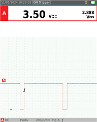
Here it is chopped down to the essentials of this problem. This code should produce a pulse train of 100ms low and 1000ms high, but it produces the opposite 100us high and 1000ss low.
How are you determining high and low? If via a led and the anode is connected to 3.3 V, it will light when the GPIO is 0 and be dark when it is high.
With a Tektronix lab grade scope! Not some USB attached toy. I am an EE of 35 years so I am well aware of electronics side.
of the problem. I suspect code optimization again interfering with standard C language operation.
I'd like to turn all this optimization off and add it as I see fit.
This is an implementation of a LCD color screen controller with 8 data lines and 5 control lines. So you can appreciate the magnitude of the problem if the processor or compiler is not properly assigning level states.
We, of course, have no idea what your experience level is.
Using this code on my MSP430FR2311:
#define bit_tst(A,B) (A & B)
#define bit_set(A,B) A |= B
#define bit_clr(A,B) A &= ~B
#define bit_tog(A,B) A ^= B

#include <msp430.h>
#include <stdio.h>

int main(void)
{
    WDTCTL = WDTPW | WDTHOLD;               // Stop watchdog timer

    //P1SEL = 0x0;
    P1OUT &= ~BIT0;                         // Clear P1.0 output latch for a defined power-on state
    P1DIR = 0xFF;                          // Set P1.0 to output direction

    PM5CTL0 &= ~LOCKLPM5;                   // Disable the GPIO power-on default high-impedance mode
                                            // to activate previously configured port settings


    while(1)
    {
        P1OUT &= ~BIT0;
        __delay_cycles(100);

        P1OUT |= BIT0;
        __delay_cycles(1000);


    }
}
I get this:

Using your Macros:
#define bit_tst(A,B) (A & B)
#define bit_set(A,B) A |= B
#define bit_clr(A,B) A &= ~B
#define bit_tog(A,B) A ^= B

#include <msp430.h>
#include <stdio.h>

int main(void)
{
    WDTCTL = WDTPW | WDTHOLD;               // Stop watchdog timer

    //P1SEL = 0x0;
    P1OUT &= ~BIT0;                         // Clear P1.0 output latch for a defined power-on state
    P1DIR = 0xFF;                          // Set P1.0 to output direction

    PM5CTL0 &= ~LOCKLPM5;                   // Disable the GPIO power-on default high-impedance mode
                                            // to activate previously configured port settings


    while(1)
    {
        bit_clr(P1OUT,BIT0);
        __delay_cycles(100);

        bit_set(P1OUT, BIT0);
        __delay_cycles(1000);


    }
}
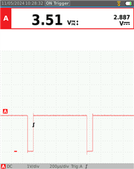
I get this:

i.e., it works for me.
Things like P1OUT might not be pointers - they might be macros themselves - so you might want to protect the expressions in your macros:
#define bitset(A,B) (A) |= (B)
In GCC at least the special function registers are #defines all the way down.
#define P1OUT (PAOUT_L) /* Port 1 Output */
sfr_b(PAOUT_L); /* Port A Output */
#define sfr_b(x) extern volatile unsigned char x
(Actually addresses are handled at link time via the linker script.)
That said, GCC was perfectly happy and output the expected bic and bis instructions.
OK I tried your modification of my code but using BIT2, and that just produces a constant high.
Now there is another .c file as well as a couple of .H files as part of the project which are the actual LCD controller driver. Bit inspecting those files there is nothing there that directly accesses the ports. And as you can see in my code there are no calls to anything in these files at this time.
In other compilers ICCAVRv8. Archimedes for legacy 8051, MPlab, this extra code is just memory waste and per what I think are normal C standards, the extra code does nothing unless specifically called functions are accessed.
Another thing, I am using the official TI LaunchPad dev board (not some offshore copy) and the pins are directly from the chip
So what is going on here?
Update:
I built a new project excluding those extra files and the same thing happens I get a constant high.
/**
 * main.c
 */

#define bit_tst(A,B) (A & B)
#define bit_set(A,B) A |= B
#define bit_clr(A,B) A &= ~B
#define bit_tog(A,B) A ^= B

#include <msp430.h>
#include <stdint.h>
#include <stdlib.h>


/************************************************************************************************************************************************/
/* Main entry point                                                                                                                             */
/************************************************************************************************************************************************/
int main(void)
{

    WDTCTL = WDTPW | WDTHOLD; // Stop wdt
/*
    P1SEL = 0x0;
    P2SEL = 0x0;
    P4SEL = 0x0;
    P1DIR = 0xFF;
    P2DIR = 0x0;
    P4DIR = 0xFC;
//    P5DIR = 0xFF;
    P6DIR = 0xFF;
//    P7DIR = 0xFF;
//    P8DIR = 0xFF;
*/

    P1OUT &= ~BIT2;
    P1DIR = 0xFF;

    PM5CTL0 &= ~LOCKLPM5;

    while(1)
    {

        bit_clr(P1OUT,BIT2);
        __delay_cycles(100);
        bit_set(P1OUT,BIT2);
        __delay_cycles(1000);
    }

//	return 0;
}I suggest either protecting the macro arguments or trying without the macros.
You can also get the basic blinky from resource explorer and make sure that works, though that might use a toggle.
Tried this, I too believe in parentheses, some call it old school but I disagree.
#define bit_tst(A,B) (A & B)
#define bit_set(A,B) (A |= B)
#define bit_clr(A,B) (A &= ~(B))
#define bit_tog(A,B) (A ^= B)
did not work.
This should pull BIT7 of P2 high and just sit there. But BIT7 stays at zero?
/**
 * main.c
 */

#define bit_tst(A,B) (A & B)
#define bit_set(A,B) (A |= B)
#define bit_clr(A,B) (A &= ~(B))
#define bit_tog(A,B) (A ^= B)

#include <msp430.h>
#include <stdint.h>
#include <stdlib.h>


/************************************************************************************************************************************************/
/* Main entry point                                                                                                                             */
/************************************************************************************************************************************************/
int main(void)
{

    WDTCTL = WDTPW | WDTHOLD; // Stop wdt
/*
    P1SEL = 0x0;
    P2SEL = 0x0;
    P4SEL = 0x0;
    P1DIR = 0xFF;
    P2DIR = 0x0;
    P4DIR = 0xFC;
//    P5DIR = 0xFF;
    P6DIR = 0xFF;
//    P7DIR = 0xFF;
//    P8DIR = 0xFF;
*/
    P2SEL = 0x0;
    P2DIR = 0xFF;
    P2OUT |= BIT7;


    PM5CTL0 &= ~LOCKLPM5;

    while(1)
    {
/*
//        bit_clr(P1OUT,BIT2);
        P2OUT |= 128;
        __delay_cycles(100);
//        bit_set(P1OUT,BIT2);
        P2OUT &= ~(128);
        __delay_cycles(1000);
*/
    }

//	return 0;
}
I must have a damaged chip?
I meant protecting the arguments like this:
#define bit_tst(A,B) ((A) & (B))
To protect against precedence issues.
Now works in this very basic form. note I commented out PM5CTL0 &= ~LOCKLPM5??
/**
 * main.c
 */
#define bit_tst(A,B) (A & B)
#define bit_set(A,B) (A |= B)
#define bit_clr(A,B) (A &= ~(B))
#define bit_tog(A,B) (A ^= B)

#include <msp430.h>

/************************************************************************************************************************************************/
/* Main entry point                                                                                                                             */
/************************************************************************************************************************************************/
int main(void)
{

    WDTCTL = WDTPW | WDTHOLD; // Stop wdt

    P1SEL = 0x0;
    P1DIR = 0xFF;
    P1OUT |= BIT2;


  //  PM5CTL0 &= ~LOCKLPM5;

while(1)
    {
    bit_clr(P1OUT,BIT2);
    __delay_cycles(100);
    bit_set(P1OUT,BIT2);
    __delay_cycles(1000);
    }

}Ok, after more hours of testing, it all boils down to this: the MSP430 or CCS just doesn't like those bit set and clear macros. If I do the bit manipulation on the fly, it works as expected. Disappointing but not a big deal.
Thanks to all here for the help and suggestions.
P.S I am using CCS version 12.
**Attention** This is a public forum